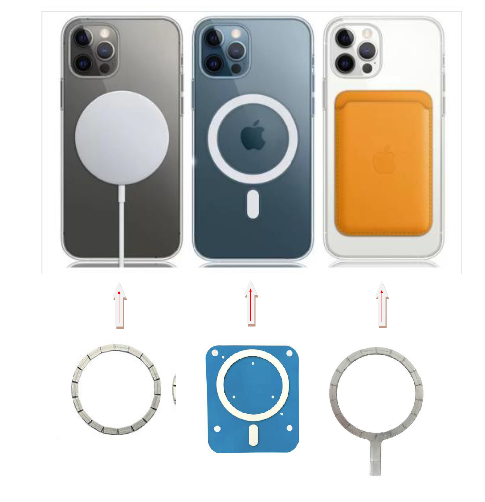
A MagSafe magnet array is a thin circular magnetic assembly used to position and retain a phone, charger, case, stand, wallet, or other accessory. Its most important job in wireless charging is repeatable alignment: it places the transmitter and receiver coils in the intended position and helps maintain that position during use.
Important distinction: the magnets do not transfer electrical power. Energy is transferred by electromagnetic induction between coils; the magnet array provides alignment, attachment, orientation, and user feedback.
What Is a MagSafe-Style Magnet Ring?
The assembly usually contains a circular array of thin permanent-magnet segments, often combined with an orientation or “key” magnet below the ring. The ring supplies centering and holding force. The key magnet helps prevent an accessory from rotating or establishes a preferred orientation.
Apple uses the MagSafe name for its ecosystem. The broader Qi2 ecosystem uses a Magnetic Power Profile based on technology contributed by Apple to the Wireless Power Consortium. Product developers should distinguish official certified products from third-party “MagSafe-compatible” or “MagSafe-style” mechanical assemblies and should confirm current licensing, certification, and interoperability requirements.
Core Working Principle
1. Magnetic self-centering
As compatible arrays approach one another, their alternating or matched pole pattern creates lateral restoring forces. If the parts are slightly offset, the magnetic field pulls them toward the lowest-energy aligned position. This “snap” makes attachment intuitive and repeatable.
2. Coil alignment
Wireless power transfer depends strongly on the relative position and spacing of the transmitter and receiver coils. Poor alignment increases leakage and loss and can generate additional heat. By constraining lateral position, the magnetic ring helps the two coils remain concentric. Apple states that magnets ensure proper alignment for wireless charging, while the Wireless Power Consortium describes magnetic positioning as a core benefit of Qi2’s Magnetic Power Profile.
3. Normal holding force
The attraction between the mating magnetic structures holds a charger or accessory against the device. Required force depends on total mass, acceleration, use angle, surface friction, case thickness, air gap, and the load applied by a cable or stand. More pull is not always better: excessive force can make removal difficult, increase impact loads, or interfere with internal components.
4. Orientation control
A lower alignment magnet or non-symmetric pole feature gives the assembly a preferred angular position. This is useful for wallets, docks, camera accessories, grips, and stands that must not freely rotate.
Main Structural Components
- Segmented arc magnets: thin NdFeB pieces arranged into a ring, with controlled polarity and spacing.
- Orientation magnet: one or more lower segments that create a rotational key.
- Carrier or adhesive layer: holds the segments at the specified pitch and protects alignment during assembly.
- Steel sheet or magnetic shield: may guide flux, reduce rear leakage, protect electronics, or tune attraction.
- Wireless-charging coil and ferrite: transfer power and manage magnetic flux associated with the charging circuit; these are distinct from the permanent magnets.
- Housing and surface layers: determine the final air gap, wear behavior, flatness, and environmental sealing.
Why Use Segmented Magnets Instead of One Solid Ring?
Segmentation allows the designer to create a defined multipole pattern using conventionally oriented pieces. It also supports thin geometry, configurable pole pitch, and scalable tooling. A one-piece multipole ring is possible in some materials and dimensions, but magnetizing-field penetration, pole precision, material utilization, and tooling can be more restrictive.
For a segmented array, the critical challenge shifts to polarity control, angular placement, adhesive consistency, coplanarity, and inspection. A single reversed segment can create a weak spot or an unintended local force.
Main Applications
| Application | Role of the magnet array | Key design concern |
|---|---|---|
| Wireless chargers | Centers and retains charging coils | Coil alignment, heat, case gap |
| Protective cases | Extends magnetic compatibility through the case | Ring position and adhesive durability |
| Power banks | Attaches the battery to the device | Shear resistance, weight, thermal path |
| Vehicle mounts | Provides quick attachment and orientation | Shock, vibration, temperature |
| Wallets and card holders | Locates and retains the accessory | Rotation control and card protection |
| Stands, grips, and tripods | Creates a detachable mechanical interface | Moment load and removal force |
| Smart-home and industrial docks | Provides blind mating and repeatable registration | Tolerance stack and cycle life |
Design Factors That Determine Performance
Air gap and stack-up
Case walls, adhesive, decorative films, coatings, ferrite, and protective covers all add separation. Magnetic force drops rapidly with gap, so the complete tolerance stack must be modeled and tested—not only the bare magnet-to-magnet condition.
Magnet grade and temperature
High remanence can improve force in a compact envelope, but coercivity and operating temperature must also be sufficient. Charging generates heat, and vehicle interiors can reach demanding temperatures. Grade selection should use the worst-case magnetic operating point rather than a room-temperature surface-field target.
Polarity and angular accuracy
The segment pattern must be compatible with the mating product. Pole sequence, magnetization direction, angular pitch, key position, and mechanical datum should be shown on the drawing. A polarity map is safer than a verbal description.
Electromagnetic compatibility
Permanent magnets, steel shields, ferrite, coils, sensors, cameras, speakers, and electronic components interact within a small volume. The design needs system-level validation. Sensitive cards, RFID devices, and medical devices also require appropriate user guidance and regulatory review.
How a MagSafe Magnet Array Is Manufactured and Tested
Typical production includes precision slicing or grinding of arc segments, coating or passivation, individual polarity verification, placement into an assembly fixture, adhesive curing, coplanarity control, and final magnetic mapping. Depending on the project, the finished array is checked for:
- Outer and inner diameter, thickness, angular position, and flatness.
- Segment polarity, pole sequence, local surface field, and magnetic moment.
- Attachment and detachment force at defined gaps and mating conditions.
- Shear resistance, rotation torque, drop, vibration, and cycle durability.
- Adhesive strength, temperature aging, humidity, and corrosion resistance.
- Functional charging alignment in the customer’s complete device.
Guande Design and Assembly Capability
Guande Magnet can support magnet selection, segmented-ring layout, pole-map review, fixture design, precision placement, adhesive process development, shielding components, magnetic mapping, and force testing. We recommend beginning with the mating geometry, allowable stack height, gap range, operating temperature, target holding force, and angular-orientation requirement.
Frequently Asked Questions
Do the magnets create wireless power?
No. The charging coils and electronics transfer and regulate energy. The permanent magnets align and mechanically retain the two sides.
Can a thicker case be compensated for with a stronger magnet?
Sometimes, but increasing magnet strength may affect removal force, mass, cost, electronics, and safety. Reducing unnecessary gap and optimizing the complete magnetic circuit are often more effective.
Is every magnetic ring automatically Qi2 certified?
No. Certification applies to the complete product and its compliance with the relevant standard, not merely to the presence of a magnet ring.
For official background, see Apple’s MagSafe charging guidance and the Wireless Power Consortium’s Qi2 overview. To develop a custom array, send Guande your pole map, geometry, gap, force target, and environmental requirements.