A one-sided magnetic product—such as a neodymium pot magnet—can deliver impressive pull force when its working face is in direct contact with a thick, flat steel plate. Yet the same assembly may feel dramatically weaker when separated by paint, plastic, rubber, a coating, a curved surface, or even a small physical clearance. This is normal magnetic-circuit behavior, not necessarily a defective magnet.
Key takeaway: a steel cup concentrates flux very effectively at contact, but its compact adjacent poles create a short-range field. Once an air gap is introduced, magnetic reluctance, field spreading, and leakage rise quickly, so useful flux at the target falls nonlinearly.
How a One-Sided Magnet Creates High Contact Force
A typical pot magnet contains an NdFeB disc or ring inside a low-carbon-steel cup. The cup redirects flux from the rear and side of the magnet to a steel rim near the front face. The exposed magnet and the surrounding rim behave as opposite poles located close together on the same working surface.
When that surface touches a sufficiently thick steel target, the target forms a low-reluctance bridge between the two poles. The magnetic path is short, leakage is limited, and flux density at the interface can be high. This is the condition under which catalogue pull-force values are normally measured.
Why a Small Gap Causes a Large Force Loss
1. Air dominates magnetic reluctance
Steel has high magnetic permeability; air does not. In a simplified magnetic circuit, reluctance increases approximately with gap length divided by pole area. Even a small gap can therefore account for most of the total reluctance. Less flux reaches the target, and the return path becomes less efficient.
2. Magnetic force depends approximately on flux density squared
For an idealized interface, magnetic pressure is often estimated by F ≈ B²A/(2μ₀). The formula is not a complete pot-magnet model, but it reveals an important relationship: if the useful flux density at the target falls, force falls even faster because force is related to the square of that field.
3. The field spreads before reaching the target
Magnetic lines emerging from the center pole and steel rim do not travel straight across a large gap. They spread outward, and part of the flux closes locally through air without entering the target. This fringing reduces the effective pole area and the useful flux density at the steel surface.
4. Adjacent poles favor short-range closure
The compact center-and-ring pole geometry that makes a pot magnet strong at contact also encourages flux to return over a short distance. As separation grows, more flux links between the adjacent poles through air instead of reaching the remote steel plate. This is why a one-sided magnet can have a steeper force-distance curve than a bare magnet designed with a longer pole spacing.
5. Real targets add further losses
Thin sheet may saturate and cannot carry all available flux. Roughness creates many microscopic gaps. Curvature reduces true contact area. Paint, powder coating, zinc, adhesive, plastic, rubber, rust, dirt, and protective films all increase effective separation. Stainless steel may be weakly magnetic or nonmagnetic depending on grade and processing.
Contact Pull Force Is Not the Same as Working-Gap Force
A catalogue value is usually measured perpendicular to a clean, flat, thick, low-carbon-steel plate under controlled conditions. It should not be used directly for an assembly with a 1 mm cover, a curved tube, a thin cabinet panel, or a shear load.
Pull-off force is a normal load. A vertical object on a wall is usually limited by friction and shear behavior. Rubber can improve friction but also increases the magnetic gap, so the net result must be tested. Peel loading at one edge can release a magnet at a much lower force than a centered perpendicular pull.
Factors That Control Force Decay
| Factor | Effect | Design response |
|---|---|---|
| Total air gap | Raises reluctance and leakage | Minimize every layer and tolerance |
| Magnet diameter | Larger pole area can improve reach | Use a larger footprint when possible |
| Pole spacing | Very close poles create a short-range field | Optimize center pole and rim geometry |
| Target thickness | Thin steel may saturate | Specify adequate low-carbon steel |
| Target shape | Curvature and roughness create gaps | Use a matching pole face or adapter plate |
| Temperature | Reduces remanence and may risk demagnetization | Select grade for worst-case temperature |
| Load direction | Shear and peel differ from pull-off | Test the actual mounting orientation |
How to Improve Force Across a Required Gap
Reduce the complete stack-up
Count all layers: coating, adhesive, housing wall, decorative film, paint, rubber, protective liner, and the mechanical clearance. Removing a fraction of a millimeter from a nonfunctional layer may produce a larger benefit than moving to a higher magnet grade.
Increase pole area or redesign the magnetic circuit
A larger-diameter assembly generally maintains useful field over a longer distance than a small one. Pole-piece thickness, center-pole diameter, cup wall, rim width, magnet thickness, and steel saturation should be optimized together. Simply installing a thicker magnet in an undersized cup can waste material.
Use an appropriate target plate
A thick, flat, low-carbon-steel target provides a much better return path than thin sheet or unsuitable stainless steel. If the original structure is nonmagnetic or too thin, a separate steel striker plate may provide a predictable mating surface.
Consider another field topology
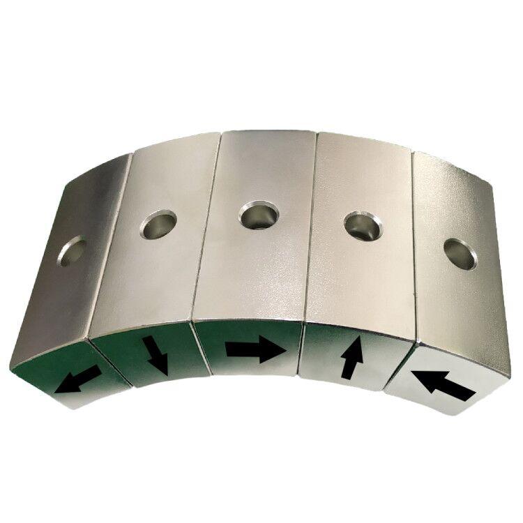
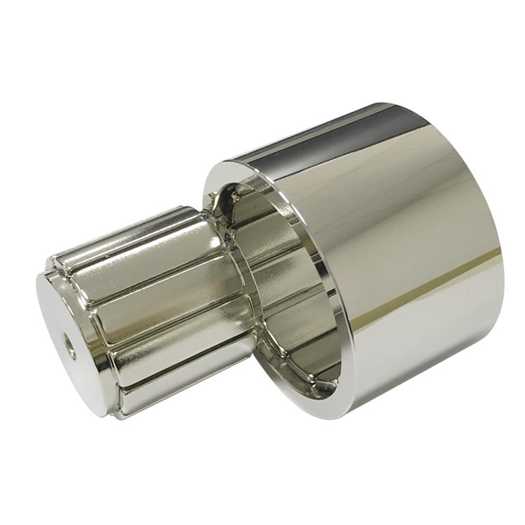
When a long working distance is essential, a pot magnet may not be the best architecture. A larger bare magnet, separated north and south poles, a bipolar assembly, a Halbach arrangement, an electromagnet, or a custom yoke can produce a more useful field at the target distance. The optimum depends on space, mass, cost, power, and safety.
Model and test at the real gap
Finite-element analysis can compare pole geometries and identify saturation or leakage. Prototype testing should then use the actual target material, thickness, surface finish, temperature, gap layers, pull direction, and loading fixture. A force-versus-gap curve is far more useful than a single contact-force number.
A Practical Specification Checklist
- Required holding force and safety factor.
- Normal pull, shear, torque, peel, or a combined load.
- Minimum, nominal, and maximum working gap.
- Target steel grade, thickness, area, curvature, and coating.
- Operating temperature, humidity, corrosion, shock, and vibration.
- Maximum envelope, mass, and allowable removal force.
- Required life cycles and acceptable cosmetic wear.
Guande Magnetic-Circuit Support
Guande Magnet can compare magnet grades, cup materials, pole geometry, shielding, target thickness, and stack-up using calculation, finite-element analysis, and application-level force testing. We also support machining, assembly, adhesive control, coating selection, and customized inspection fixtures.
Frequently Asked Questions
Does a higher NdFeB grade always solve the air-gap problem?
No. It may help, but the result can be limited by leakage, pole geometry, steel saturation, temperature, and target thickness. Circuit optimization often produces a better cost-to-force result.
Why does a rubber-coated pot magnet sometimes hold better on a wall?
Rubber increases friction, which helps resist shear, but it also increases the magnetic gap and reduces normal pull. The final result depends on both effects.
Can contact pull force be converted to force at 2 mm with a fixed percentage?
No reliable universal percentage exists. The curve depends on diameter, pole geometry, magnet grade, steel cup, target, and measurement method.
Send Guande the target material, gap stack, load direction, temperature, and required force to receive a practical magnetic-circuit review instead of relying on a contact-force value alone.