
Sintered NdFeB Magnets / Block Magnets
Neodymium Block Magnets: Dimensions, Magnetization and Machining
Block magnets provide flexible pole-face proportions and are widely used in linear motion, sensing, holding and magnetic arrays. This page explains how length, width, thickness, magnetization axis and edge details should be defined for a stable production specification.
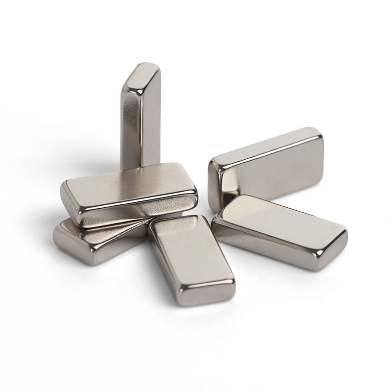
Geometry and Dimension Definition
Use functional datums and define the magnetization reference on the drawing. The table below provides the minimum geometry information for a practical manufacturing review.
| Parameter | How to define it | Why it matters |
|---|---|---|
| L — Length | Longest plan dimension | Defines array pitch, travel length or assembly envelope |
| W — Width | Second plan dimension | Controls pole width and lateral fit |
| T — Thickness | Dimension through the shortest axis in most designs | Frequently selected as the magnetization direction |
| Edge features | Chamfer, radius, slot, step or hole | Must include datum, size and orientation on the drawing |
Design Considerations
Magnetization through T, W or L
The chosen axis changes the pole-face area and magnetic working length. It must match the intended magnetic circuit rather than simply the shortest dimension.
Pole-face aspect ratio
Long, narrow pole faces can create non-uniform field distribution near the ends. Sensor location or air-gap geometry should be considered early.
One long block or several segments
Segmenting a long block can reduce breakage risk and ease magnetization, but introduces gaps and additional assembly control.
Manufacturing and Assembly Notes
- Long, thin blocks are sensitive to bending and impact during grinding, coating, transport and assembly.
- Square corners chip easily; chamfers or small radii improve handling robustness.
- Slots, steps and holes reduce local cross-section and may require relaxed tolerances or an alternative assembly design.
- Orientation marking is recommended when the geometry does not make magnetization direction obvious.
Typical Applications
Linear motors and actuators
Controlled pitch and polarity for force generation along a travel path.
Magnetic arrays
Matched dimensions and magnetic moment for Halbach arrays, fixtures and field shaping.
Industrial sensors
Defined pole faces for Hall, reed and magnetoresistive sensing.
Separation and holding
High pole-face area in compact separators, clamps and workholding systems.
Engineering Questions
Which dimension should be magnetized?
Choose the axis that gives the required pole location, air-gap field and assembly orientation. Magnetizing through thickness is common, but through-width or through-length designs can be better for side-facing fields.
When should a long block be segmented?
Segmentation is worth reviewing when handling risk, magnetization capacity, coating yield or assembly stress becomes difficult to control with one piece.
How tight can L×W×T tolerances be?
Ground dimensions of ±0.05 mm are common starting points, but size, aspect ratio, coating and inspection method determine what is economical and repeatable.
Are sharp corners recommended?
Usually not. A small chamfer protects the coating and reduces edge chipping without materially changing most magnetic circuits.
For a focused design review, share your drawing, operating temperature, air gap, target magnetic performance and annual volume through our enquiry page. You can also return to Sintered NdFeB Magnets for material-level guidance.