
Magnetic Assemblies / Halbach Arrays
Halbach Arrays: Directed Flux Through Controlled Magnetization
A Halbach array rotates magnetization direction from segment to segment to strengthen the field on one side while reducing it on the other. Useful performance depends on segment geometry, orientation accuracy, gaps and assembly fixtures.
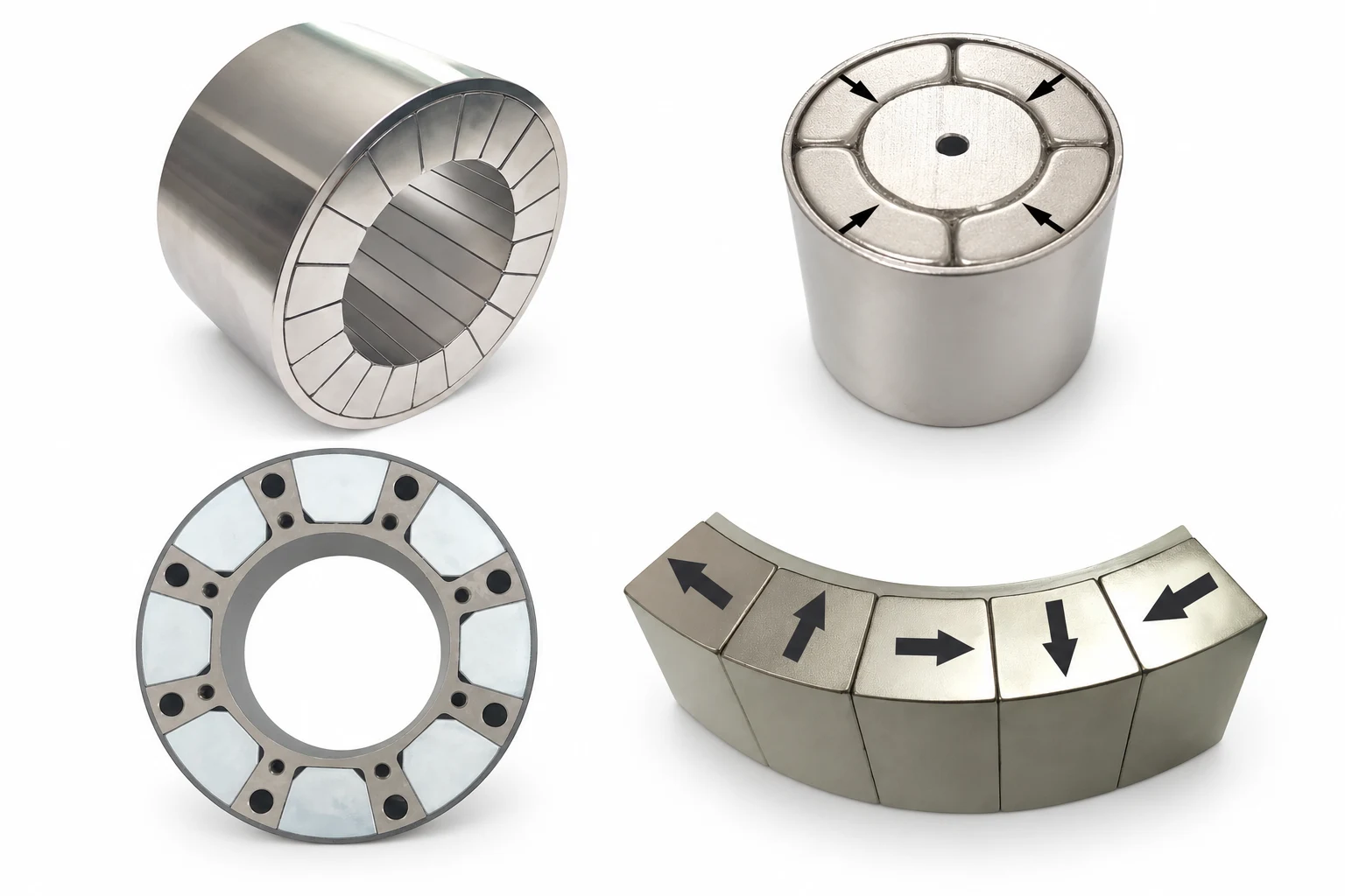
CUSTOM HALBACH ARRAY · ORDERING GUIDE
From Your Field Requirement to a Verified Sample
Follow these five steps to define, simulate and validate your custom Halbach array. Send us your application requirements to start the engineering review.
- 01
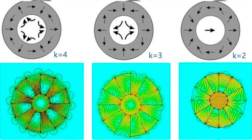
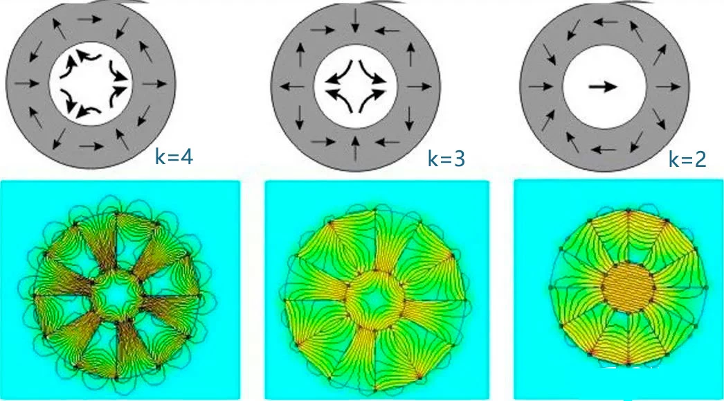
Reference configurations; the K notation follows the supplied diagram. Field Requirements
Define the field pattern
Share the field configuration you need: K = 2, K = 3 or K = 4, using the reference diagram or your own field map. Include the bore, outer diameter, axial length, working region and operating temperature.
Your input: application, drawing and required field pattern.
- 02
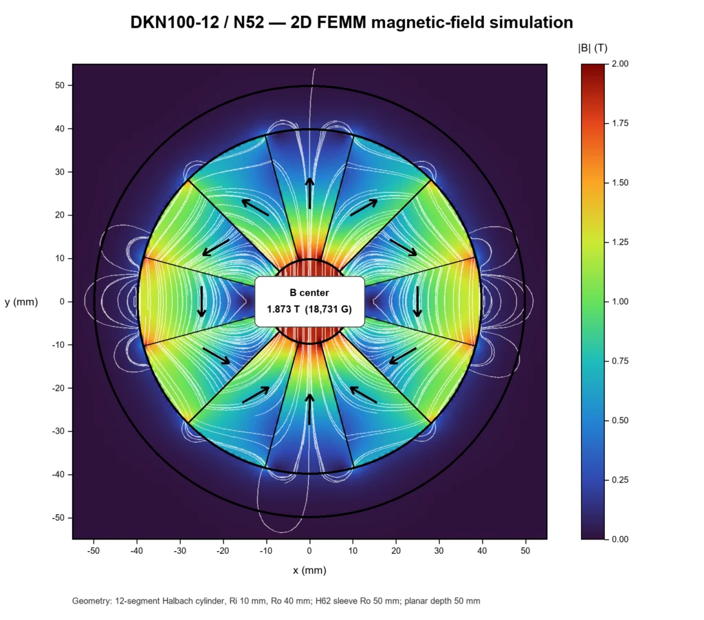
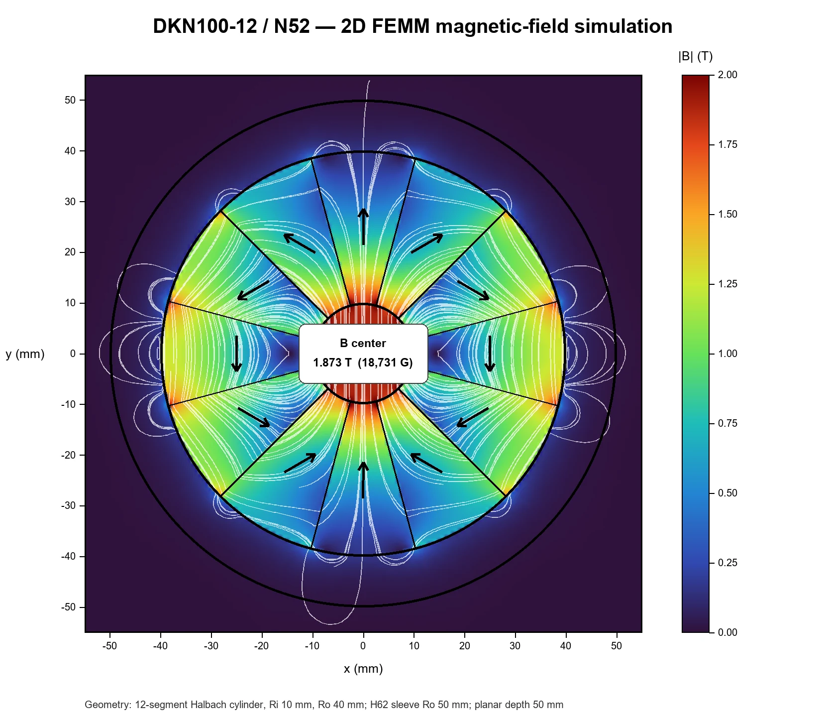
Illustrative simulation: DKN100-12 / N52. The displayed value is specific to this model. Target Field & Simulation
Review the magnetic-field simulation
Specify the target flux density in T or G, measurement position, working gap and field-uniformity requirement. We prepare a magnetic-field simulation for your geometry and review the predicted distribution with you before prototype approval.
Review output: proposed geometry, magnetization layout and simulated field map.
- 03
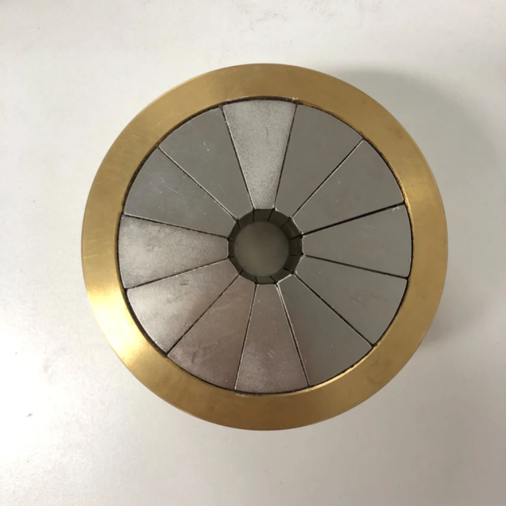
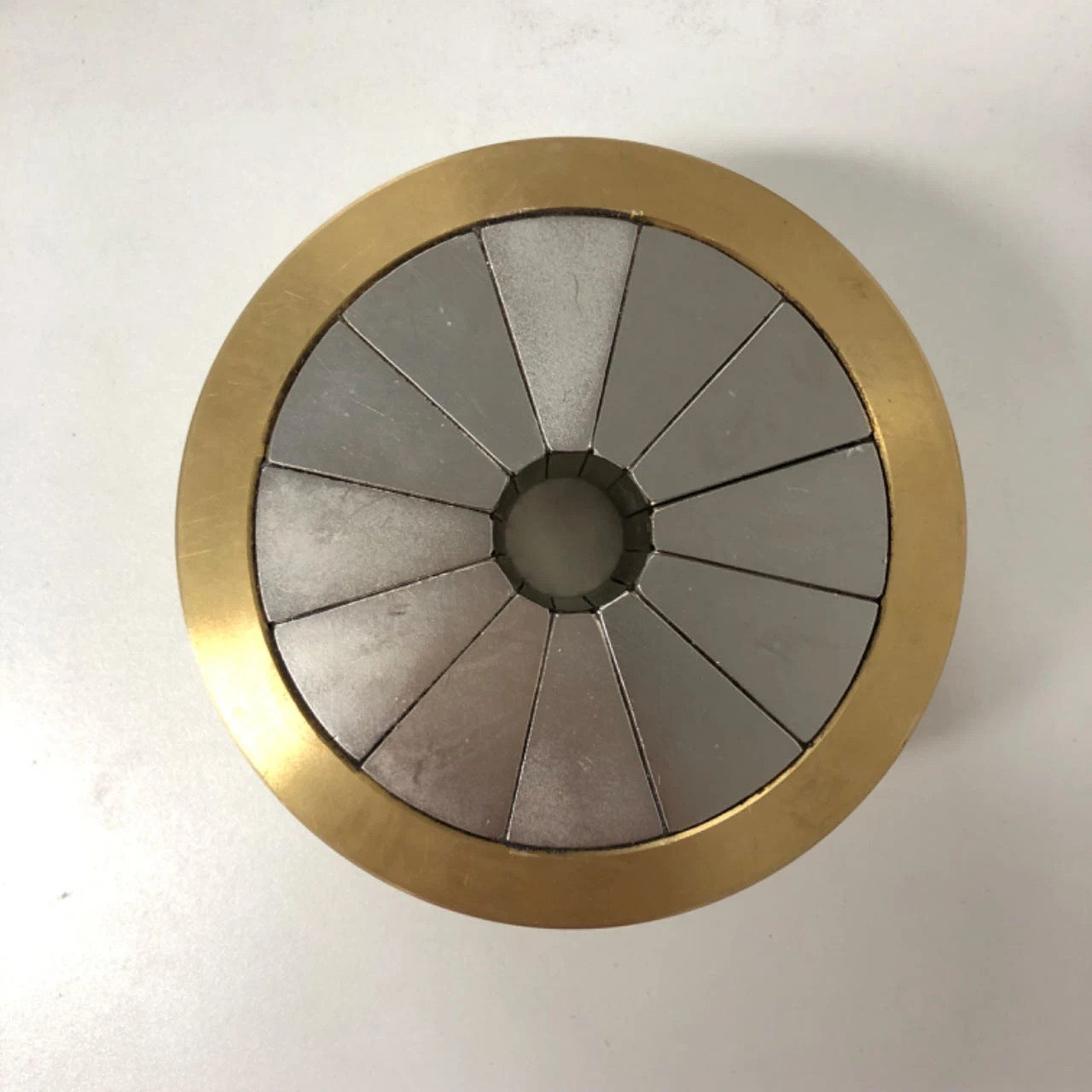
Example of an assembled segmented ring in its supporting sleeve. Prototype Manufacturing
Build the approved sample
After the drawing, magnetization sequence and quotation are agreed, we manufacture and assemble the sample. Segment positioning, bonding gaps and the supporting sleeve follow the approved design.
Review output: a prototype for measurement and application evaluation.
- 04
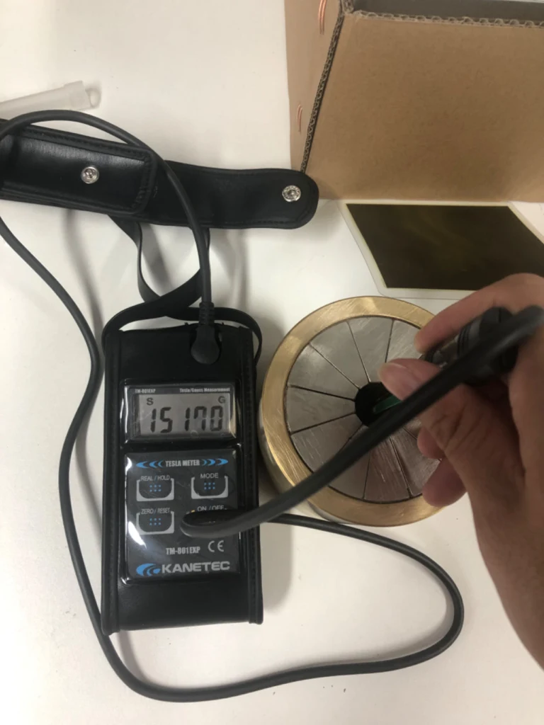
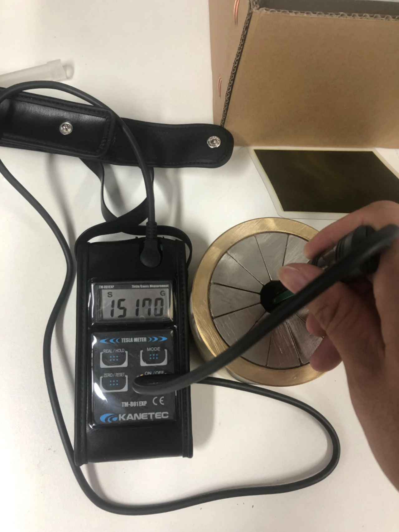
Example test photograph. Its meter reading is not a guaranteed value for other designs. Magnetic-Field Testing
Measure the sample field
We measure the prototype with a gaussmeter at agreed locations and probe orientations, then compare the results with the target specification. Measurement conditions are recorded for a meaningful comparison.
Review output: measured field values against agreed acceptance points.
- 05
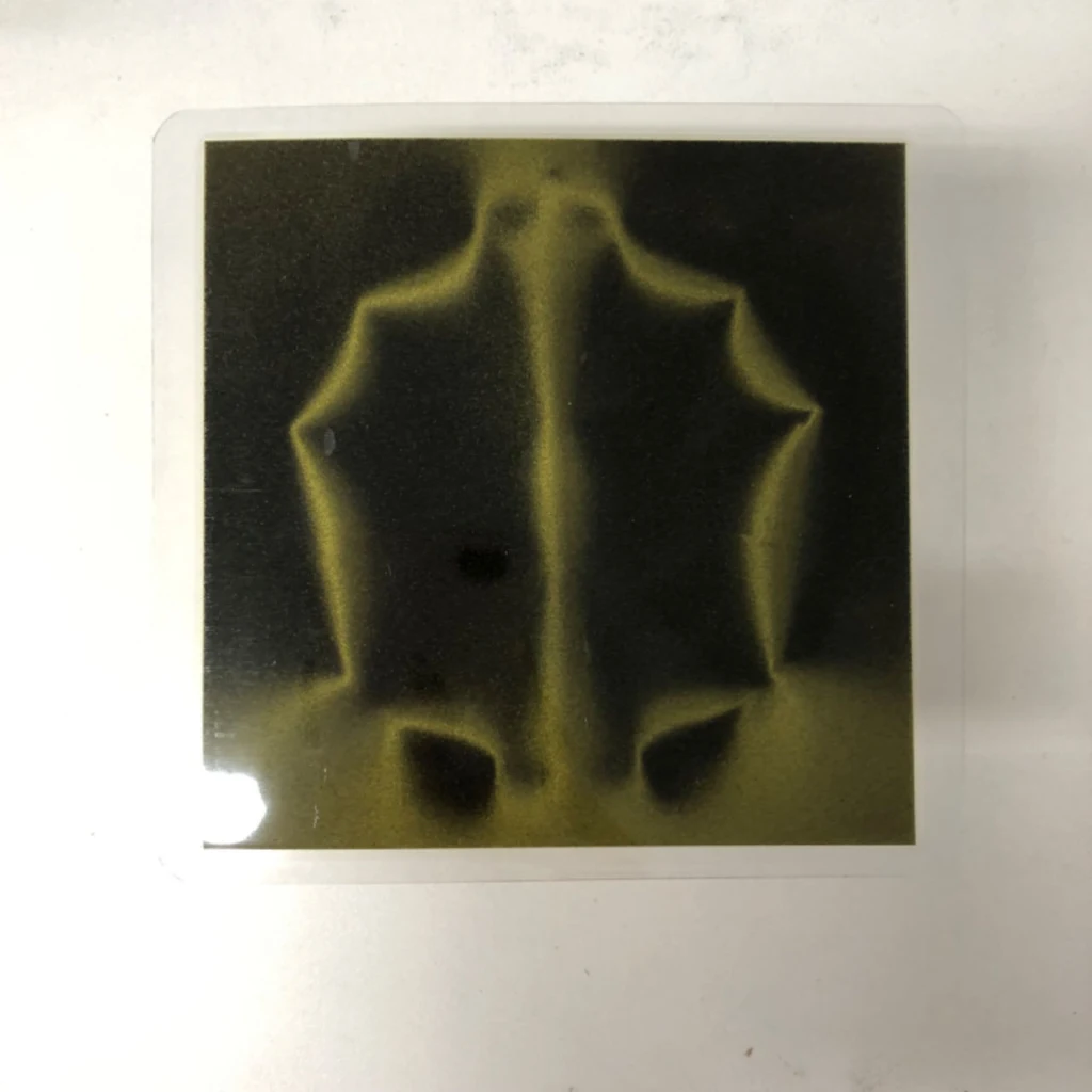
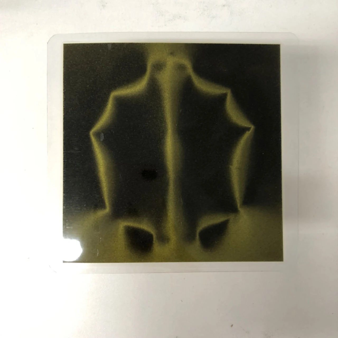
Viewing film shows the field pattern; quantitative strength is checked with a calibrated meter. Magnetic-Circuit Verification
Check the field pattern
Use magnetic viewing film to inspect the visible pole pattern and compare it with the intended magnetic arrangement. Combine this qualitative check with the measured field data and application evaluation before approving repeat production.
Next step: confirm sample acceptance and the production requirements.
Start Your Halbach Array Enquiry
Send your drawing, K configuration or field map, target field, measurement location, temperature and required quantity.
Geometry and Dimension Definition
Use functional datums and define the magnetization reference on the drawing. The table below provides the minimum geometry information for a practical manufacturing review.
| Parameter | How to define it | Why it matters |
|---|---|---|
| Array length / diameter | Finished linear or circular envelope | Defines the working field region |
| Segment geometry | Block, trapezoid or arc dimensions | Controls approximation of the ideal magnetization rotation |
| Magnetization angle | Direction for every numbered segment | Primary functional specification |
| Gap and support | Bondline, carrier and locating features | Controls field uniformity and mechanical stability |
Design Considerations
Segment count
More orientations can improve field concentration but increase parts, gaps and assembly complexity.
Orientation accuracy
Magnetization angle and physical placement errors directly reduce the intended one-sided effect.
Back iron and surroundings
Nearby steel changes the field distribution and must be included in modeling and tests.
Manufacturing and Assembly Notes
- Strong repulsive forces make uncontrolled assembly unsafe.
- One reversed segment can materially distort the field.
- Bondline accumulation changes pitch and circular closure.
- Custom magnetization fixtures may determine prototype lead time.
ASSEMBLY PROCESS
Watch: 12-Segment Halbach Ring Assembly
This 41-second demonstration shows how spacer fixtures with holes help control segment position, assembly gaps and orientation while the ring is closed. The fixture supports repeatability, but the magnetization direction of every numbered segment must still be verified before bonding.
Video hosted on the Guande Magnet YouTube channel. The YouTube player loads only after you click play.
Typical Applications
Linear motors
High working-side field with reduced back-side leakage.
Magnetic bearings
Directed fields for non-contact support.
NMR and sensing
Compact field-shaping arrays.
Robotics and transport
One-sided attraction and magnetic wheel systems.
Engineering Questions
How many segments are needed?
It depends on field quality, size, available orientations, assembly cost and tolerance budget.
Can standard axially magnetized blocks be used?
Some simplified arrays can, but the intended field may require multiple magnetization directions.
Why are assembly fixtures essential?
They control position and prevent magnets from rotating or ejecting under strong mutual forces.
How should the array be accepted?
Define a field map or measurements at functional locations, not only individual magnet surface readings.
For a focused design review, share your drawing, operating temperature, air gap, target magnetic performance and annual volume through our enquiry page. You can also return to Magnetic Assemblies for material-level guidance.