
Magnetic Assemblies / Pot Magnets
Pot Magnets: Compact Steel-Cup Holding Systems
Pot magnets combine a permanent magnet with a ferromagnetic cup to concentrate flux at one working face. Selection should be based on the real contact surface, air gap, load direction and mounting method—not a catalogue pull-force number alone.
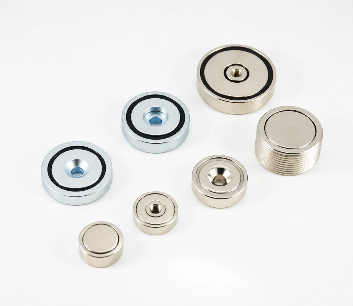
Pot Magnet Designs and Mounting Options
Our pot magnet design and manufacturing experience covers housing textures, locating features, filling methods and mounting interfaces. Compare the examples below, then specify the combination that fits your product.
Select a thumbnail to view the detail. Images illustrate the construction; dimensions, fill material and performance are confirmed in the project specification.
Housing Details and Assembly Features
| Design example | Design and process focus | Typical use |
|---|---|---|
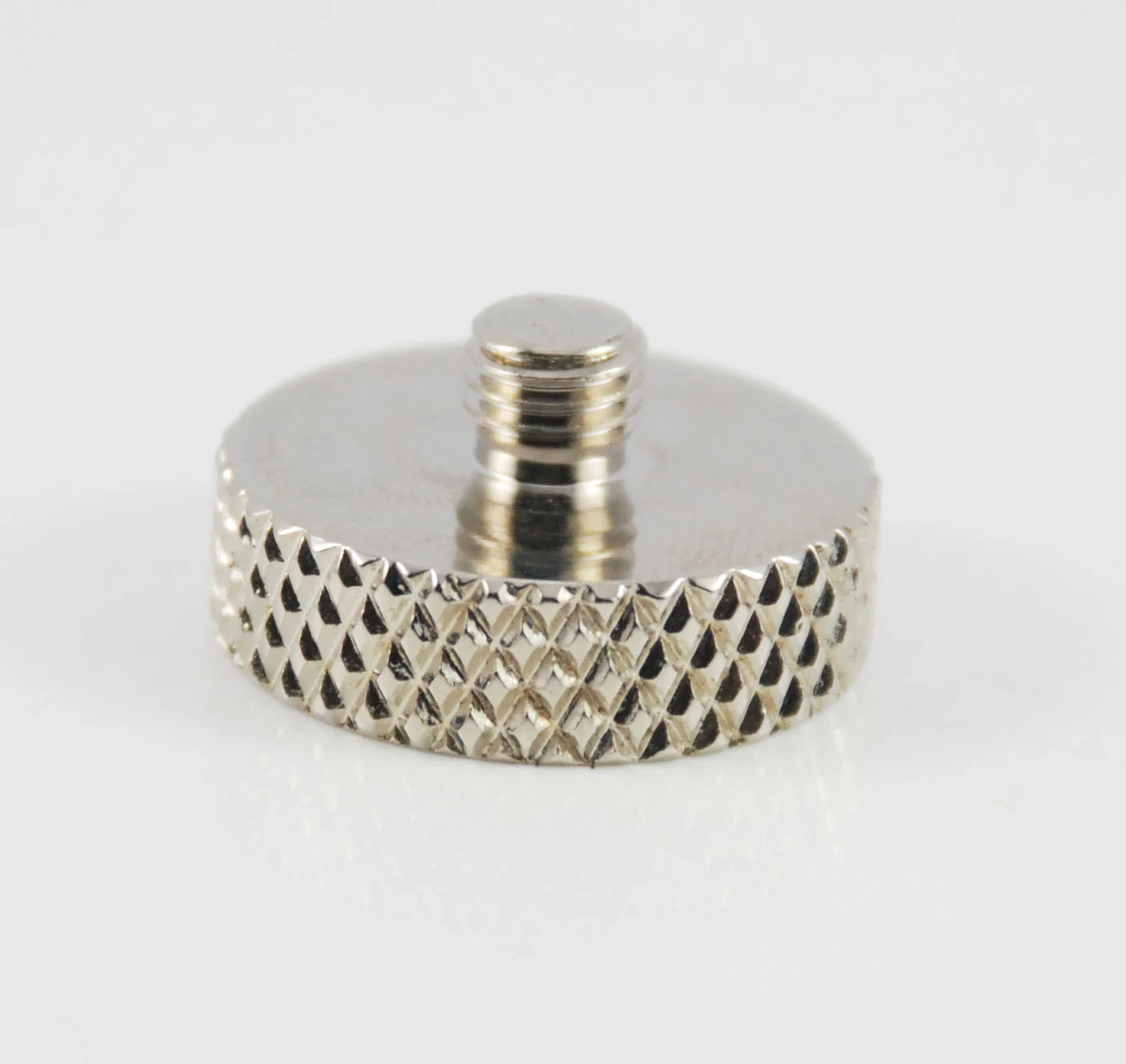 | A textured perimeter improves hand grip and can support anti-rotation in a designed mating interface. Knurl depth and finished diameter are controlled together. | Hand-adjusted fixtures, removable mounts and assembly into a matching carrier. |
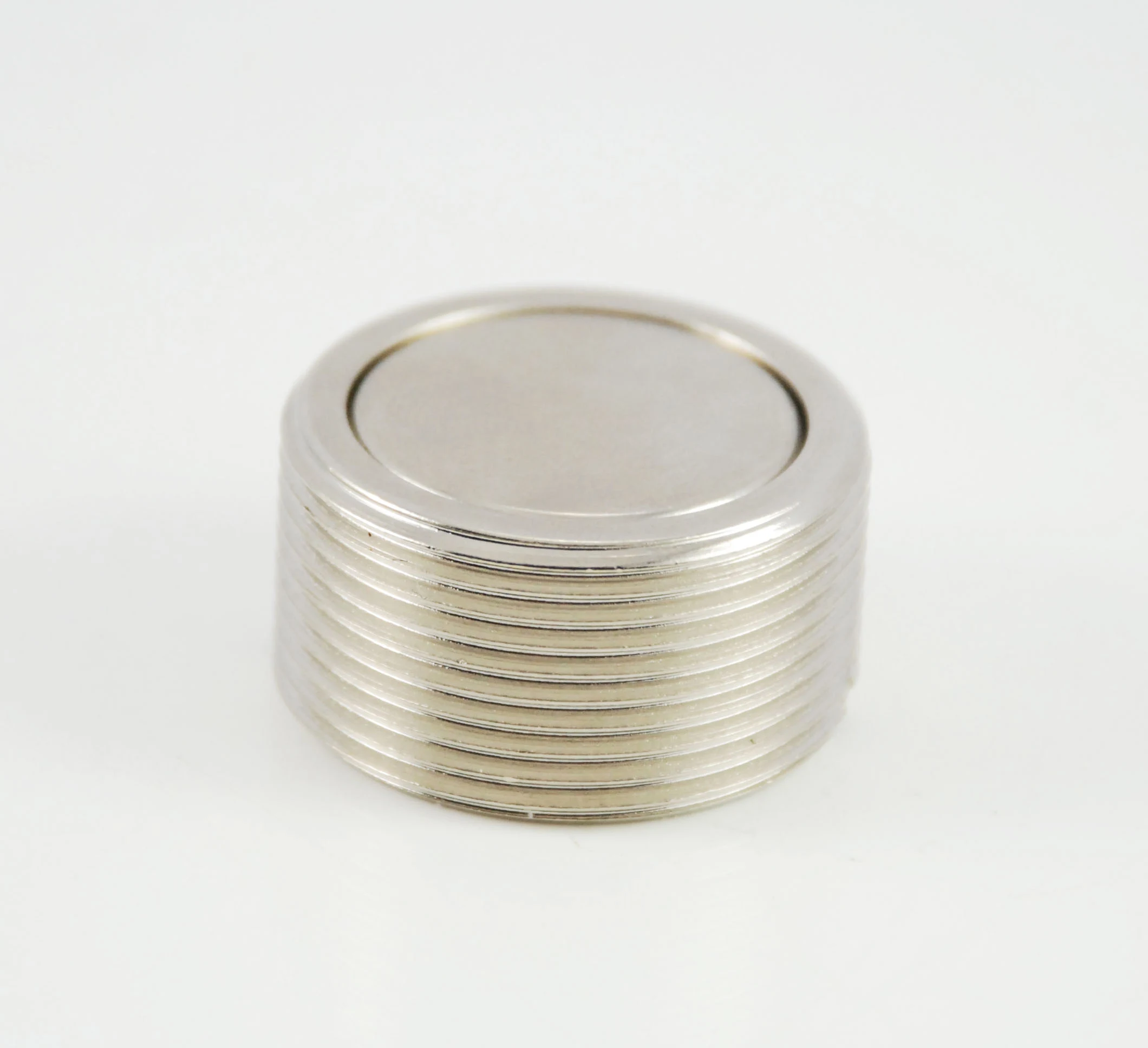 | Repeated perimeter grooves provide a defined interface for bonding, moulding or mechanical retention. Groove pitch, depth and fit are specified for the mating part. | Embedded magnetic inserts and retained assemblies. Retention depends on the complete joint design. |
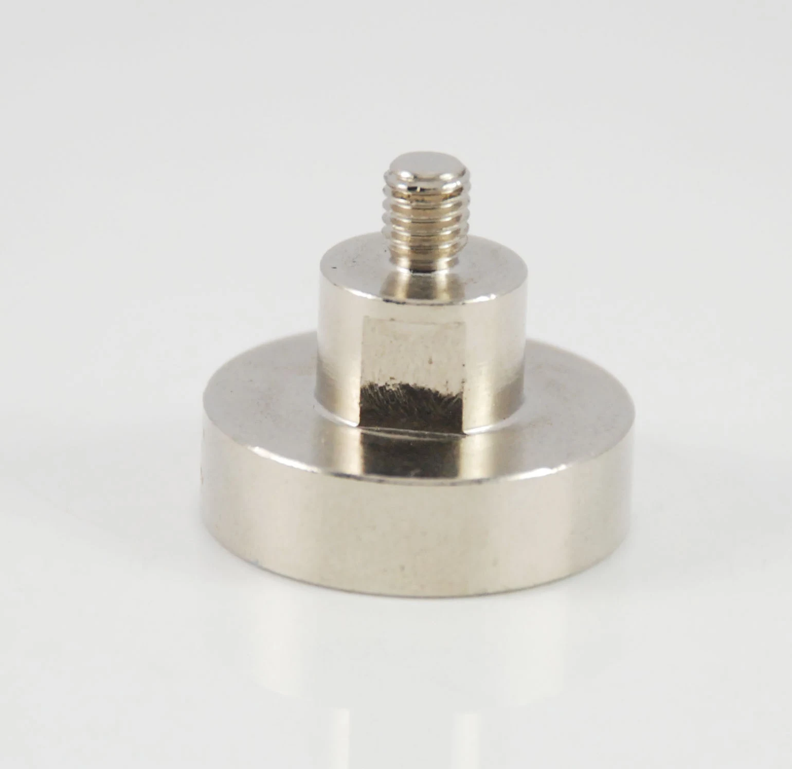 | A shoulder sets seating depth and locates the assembly. Boss diameter, height and concentricity control the mating fit. | Recessed mounting, stand-off positioning and fixture assemblies requiring a positive locating shoulder. |
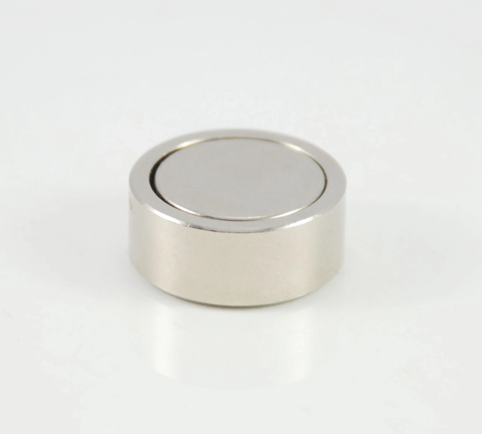 | A smooth outside diameter supports a clean pocket fit. Diameter, coating build and adhesive clearance are reviewed together. | Bonded inserts, closures and flush-mounted holding points. |
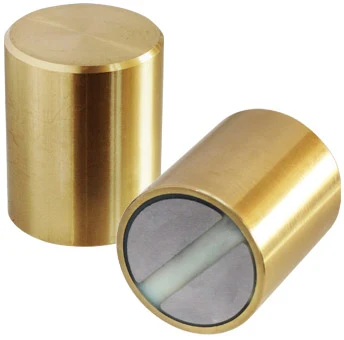 | A deeper housing accommodates a different pole layout and installation envelope. Pole geometry and working-face contact are reviewed as a complete circuit. | Tooling and positioning applications where a deep cylindrical envelope suits the equipment. |
Filling and Spacer Options
| Design example | Design and process focus | Typical use |
|---|---|---|
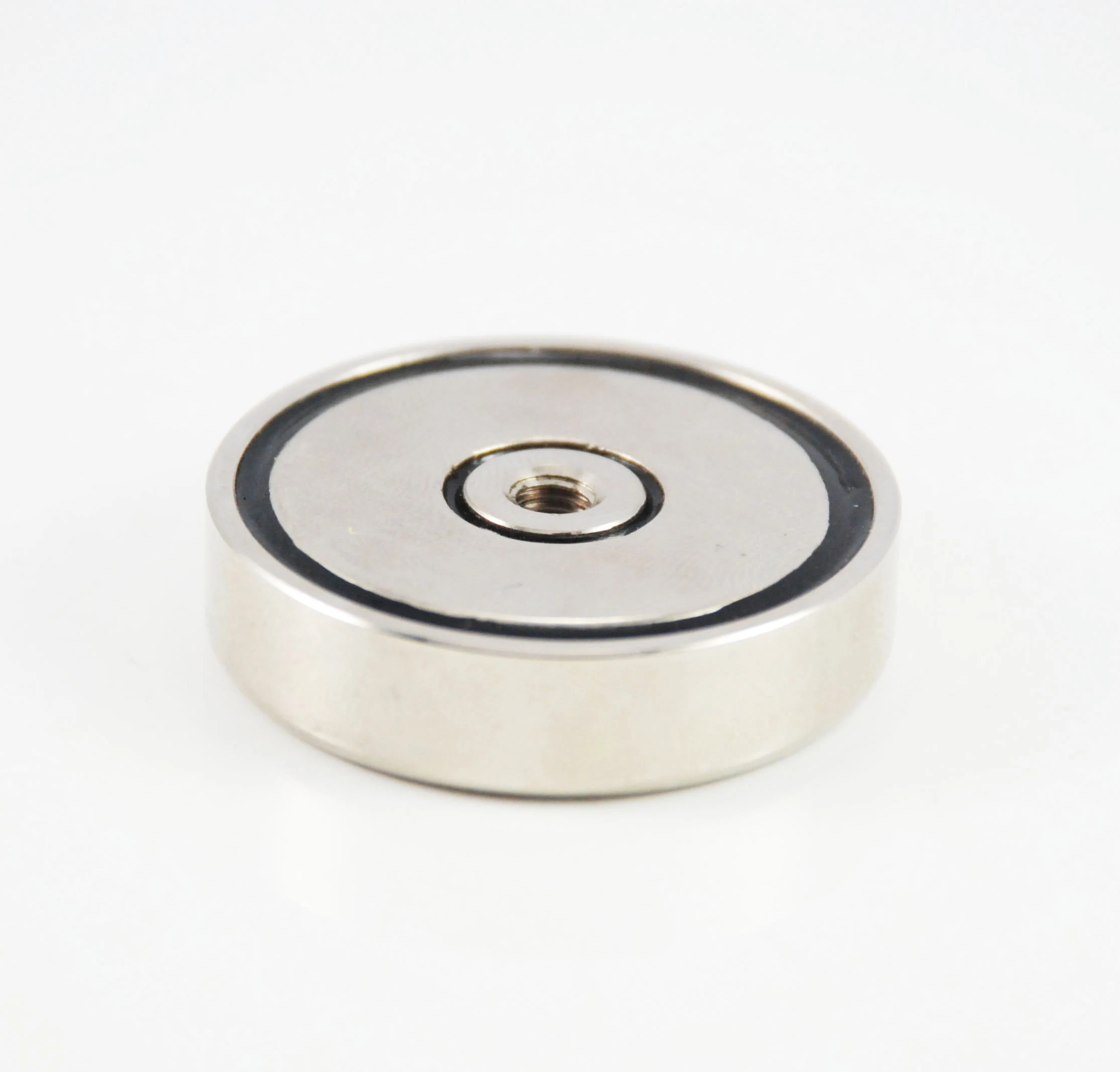 | Resin can fill the specified gap and support the magnet. Fill height, trapped air, cure conditions and the finished contact plane require process control. | Bonded assemblies requiring controlled gap filling and protection suited to the agreed exposure. |
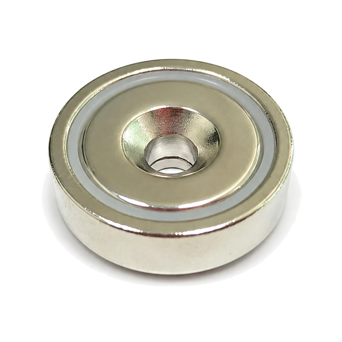 | A formed non-magnetic ring defines spacing between magnet and cup. Ring dimensions, material compatibility and retention are matched to the assembly. | Repeatable component positioning and assemblies using a defined spacer rather than a poured fill. |
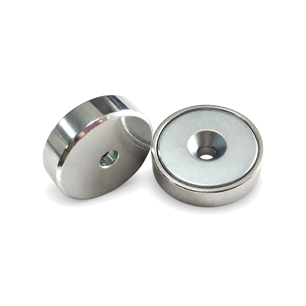 | A close-fitting face can be designed without an exposed resin or plastic ring. The internal retaining method and clearances are still specified. | Compact mounting points with a simple face layout; environmental protection is assessed separately. |
Threads and Mounting Holes
| Design example | Design and process focus | Typical use |
|---|---|---|
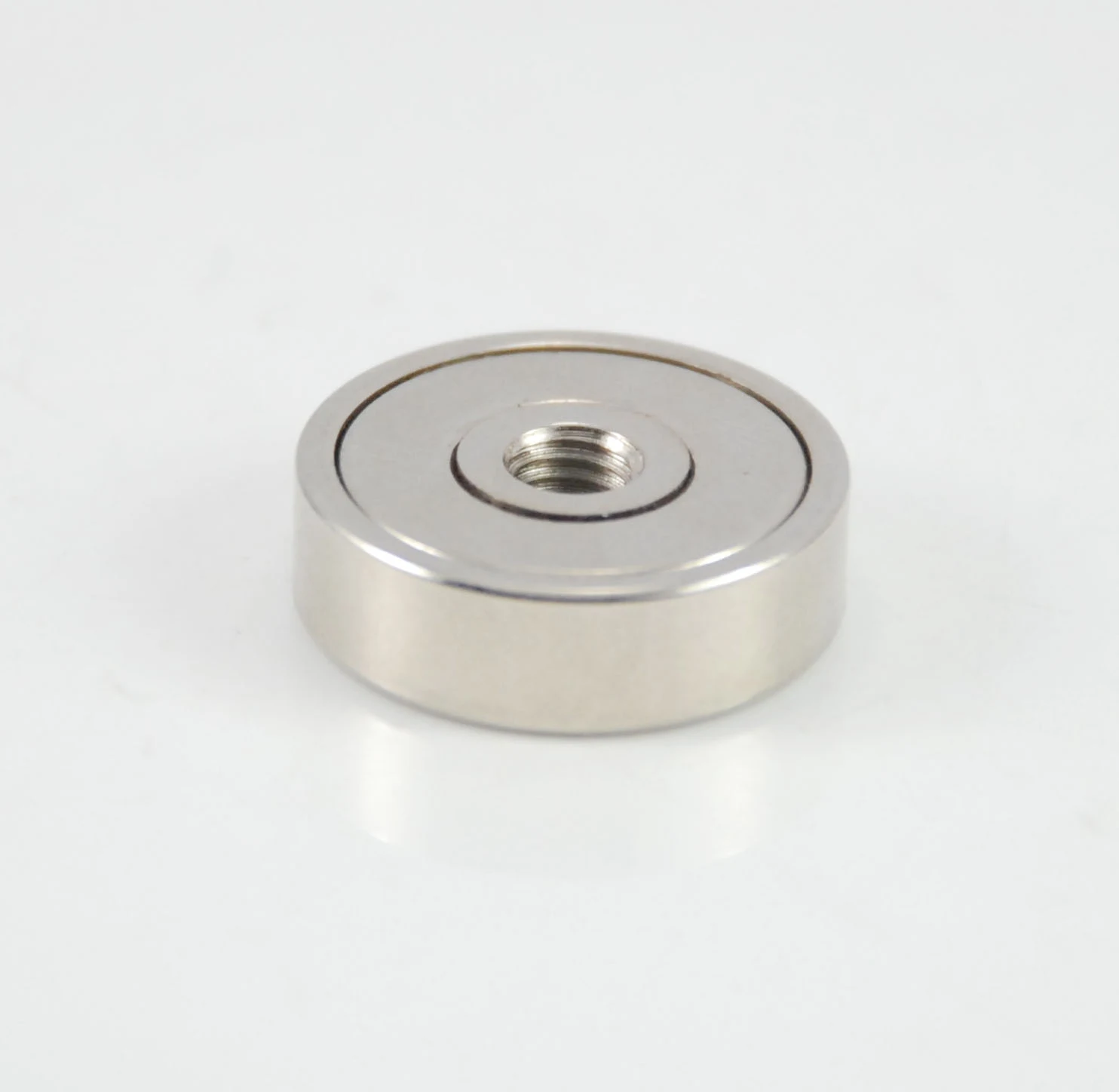 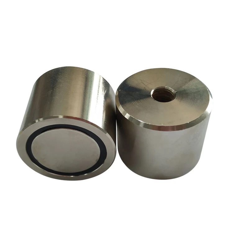 | A tapped centre or rear mounting hole connects to a screw or threaded accessory. Thread size, engagement and usable depth are specified. | Fixture plates, handles and modular tooling with removable threaded connections. |
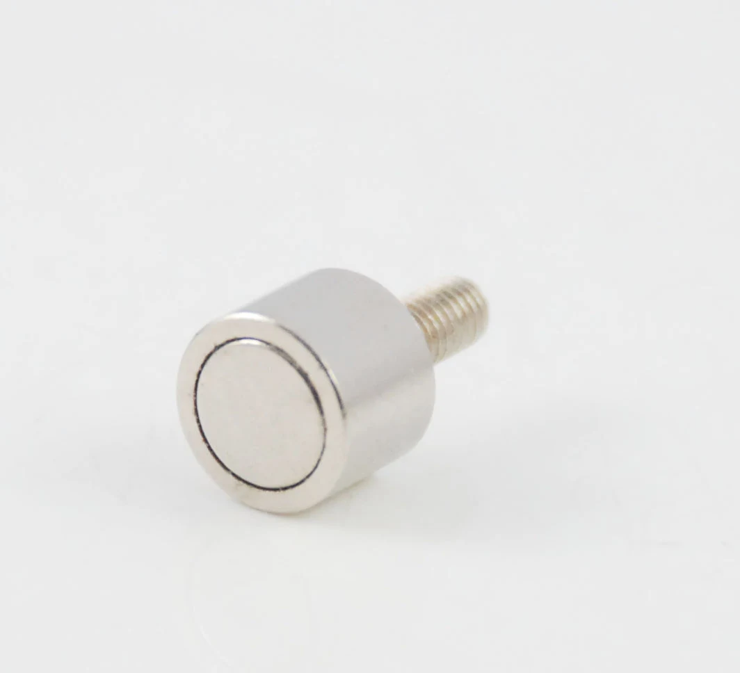 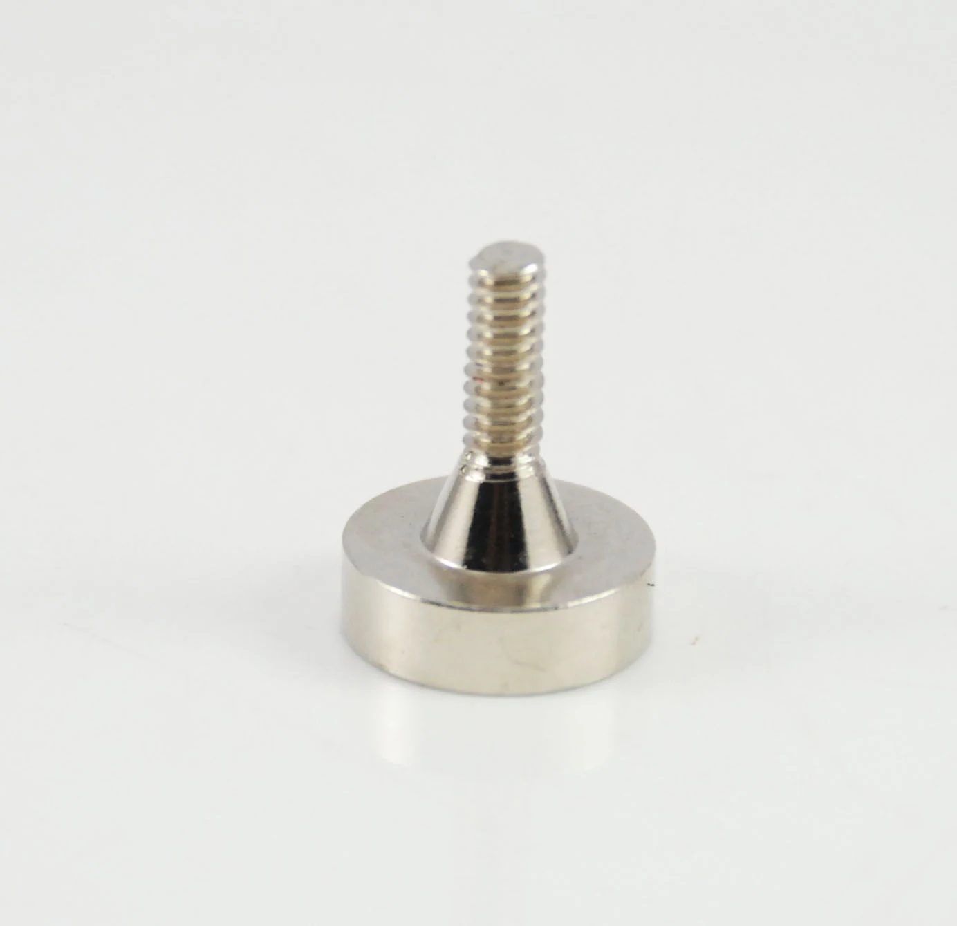 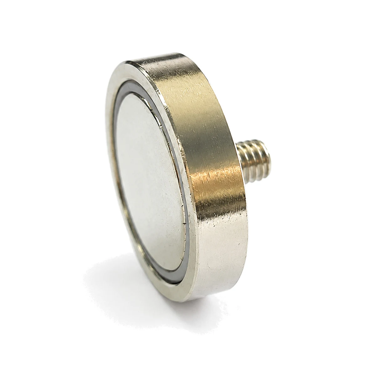 | A male thread allows direct connection to a tapped component or nut. Stud length, projection and shoulder geometry suit the host assembly. | Sensor brackets, lighting mounts, signs and adjustable fixtures. |
| A conical recess accommodates the matching screw head. Hole diameter, countersink angle and head clearance determine the fit. | Low-profile fixing to panels or tooling where the fastener must remain below the working face. |
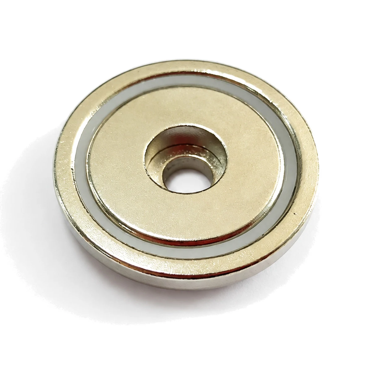 | A stepped cylindrical recess provides space for a compatible screw head, with a smaller hole passing through the assembly. Plain through-hole variants can be specified to drawing. | Bolted fixtures and equipment mounts; screw-head size, recess depth and tool access are reviewed together. |
Knurling and grooves act at the handling or mating interface; they do not automatically increase magnetic pull force. A locating shoulder supports assembly positioning. Fill selection does not by itself establish a waterproof rating.
From a Mounting Detail to a Repeatable Assembly
Send the mating-part drawing, installation method and operating conditions. We coordinate cup machining, thread and hole geometry, magnet fit, filling or spacer selection and inspection so the prototype can become a defined repeat-production part.
Discuss Your Pot Magnet DesignGeometry and Dimension Definition
Use functional datums and define the magnetization reference on the drawing. The table below provides the minimum geometry information for a practical manufacturing review.
| Parameter | How to define it | Why it matters |
|---|---|---|
| D — Cup diameter | Finished outside diameter | Defines contact area and installation envelope |
| H — Overall height | Cup, magnet and any boss or thread | Controls recess depth and mechanical clearance |
| Mounting interface | Countersunk hole, internal thread, stud or plain back | Transfers the external load into the structure |
| Working face | Flatness, coating and exposed pole arrangement | Controls the effective air gap and holding force |
Design Considerations
Steel-cup magnetic circuit
The cup redirects return flux to the working face and protects the magnet, but cup thickness and steel grade must avoid saturation.
Rated pull force
Force data should state steel thickness, surface finish, loading direction and test method. Thin or painted steel can reduce performance sharply.
Mounting and load path
The screw or thread should carry service loads without placing tensile or bending stress into the brittle magnet.
Manufacturing and Assembly Notes
- Side loads are much lower than direct pull unless a mechanical stop is provided.
- An air gap from paint, dirt, curvature or roughness reduces holding force.
- Over-tightening a countersunk fixing can damage the magnet or distort the cup.
- Impact attachment can chip the exposed magnetic face.
Typical Applications
Fixtures and jigs
Compact removable holding points for production equipment.
Doors and access panels
Reliable closures with a defined steel target.
Sensors and lighting
Threaded or countersunk mounting for repositionable devices.
Retail and display systems
Reusable attachment without drilling the target surface.
Engineering Questions
Why is a pot magnet stronger than the bare magnet?
The steel cup concentrates usable flux at one face and provides a low-reluctance return path. The improvement depends on cup design and the target steel.
Why is real-world holding force lower than the catalogue value?
Air gaps, thin steel, side loading, surface curvature and incomplete contact all reduce force. Test the complete joint.
Can a pot magnet work at elevated temperature?
Yes, with a suitable magnet grade, adhesive and coating. Rate the complete assembly, not only the NdFeB material.
Should I choose a stud, thread or countersunk hole?
Choose the interface from installation access, load direction, serviceability and allowable tightening torque.
For a focused design review, share your drawing, operating temperature, air gap, target magnetic performance and annual volume through our enquiry page. You can also return to Magnetic Assemblies for material-level guidance.