
Magnetic Assemblies / Rubber Coated Magnets
Rubber Coated Magnets: Surface Protection, Grip and Outdoor Durability
Rubber coating can protect an individual magnet or a complete magnetic assembly. We combine surface protection and grip with custom carriers, mounting interfaces and controlled moulding—from compact accessory mounts to large rectangular holding assemblies.
Construction and Custom Formats
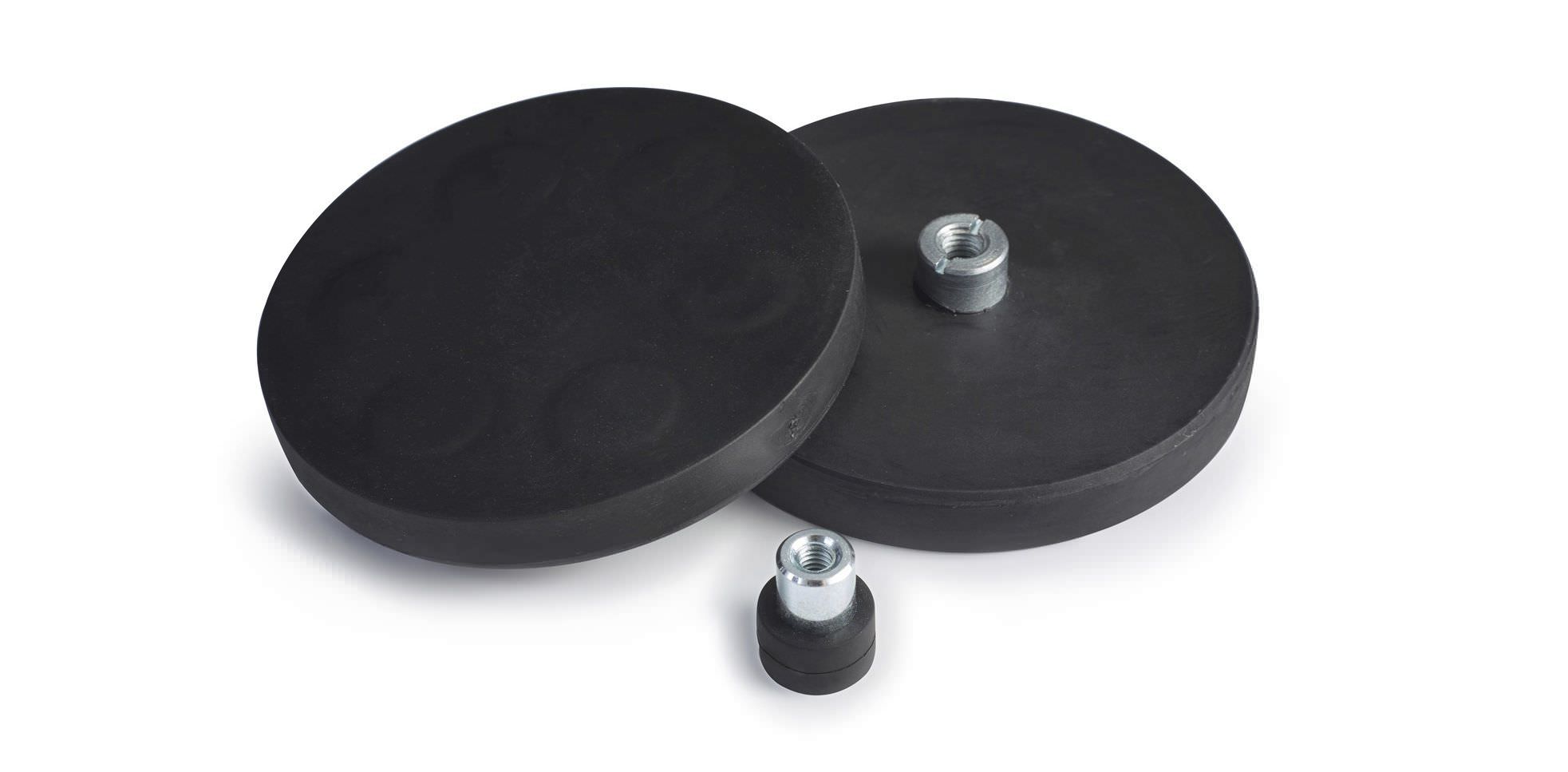
Individual magnets can receive a protective cover, while magnetic assemblies typically use a steel carrier to locate the magnets and form the magnetic circuit. The outside is coated in rubber, leaving the required fixing interfaces accessible. Internal threads, external studs and side-mounted threads are selected around the equipment design.
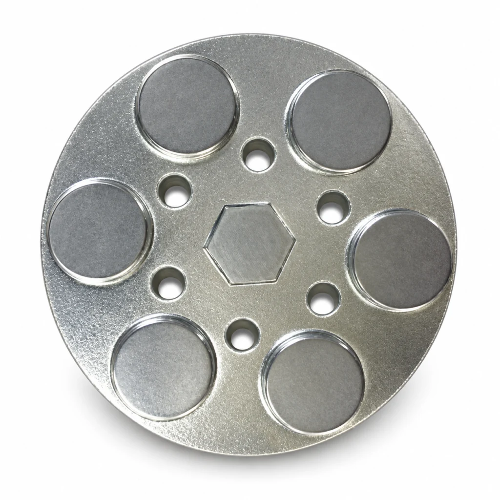
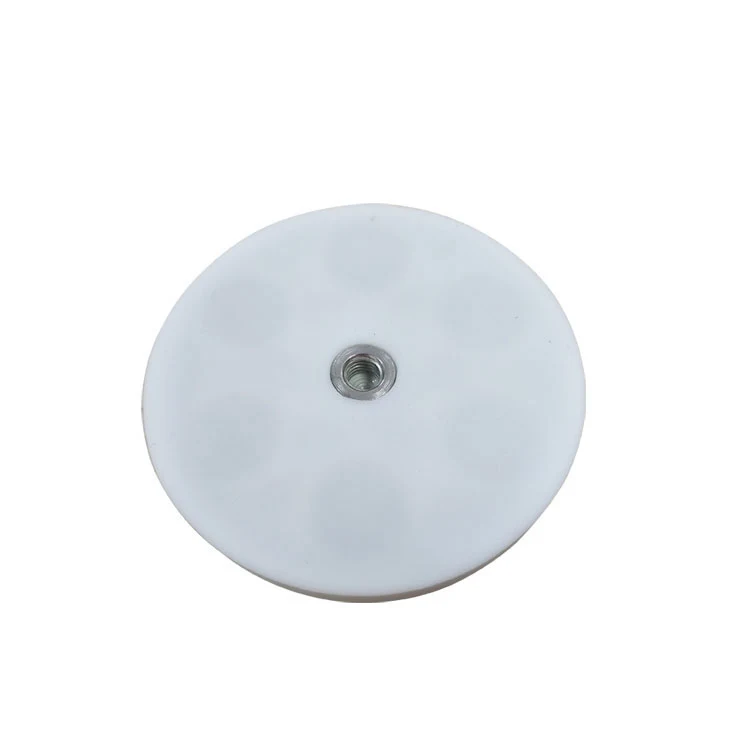
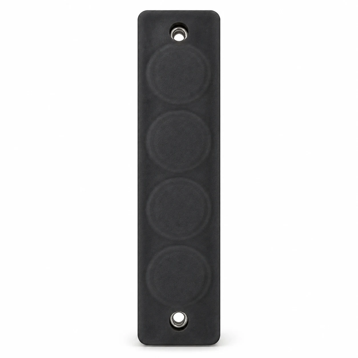
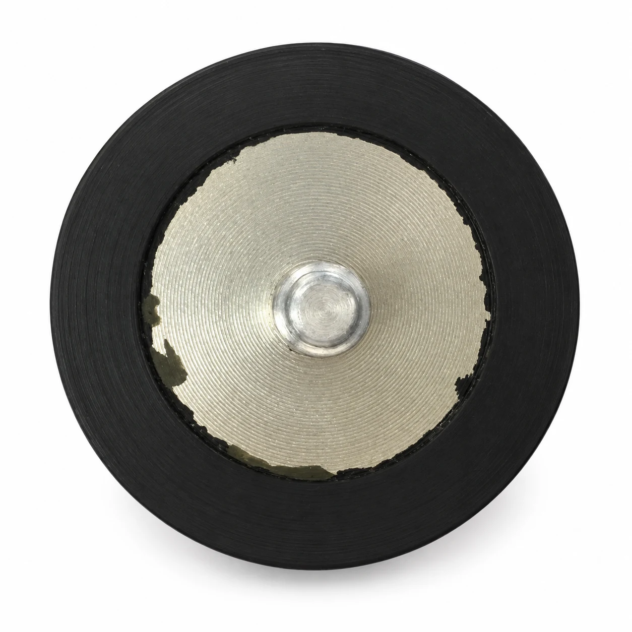
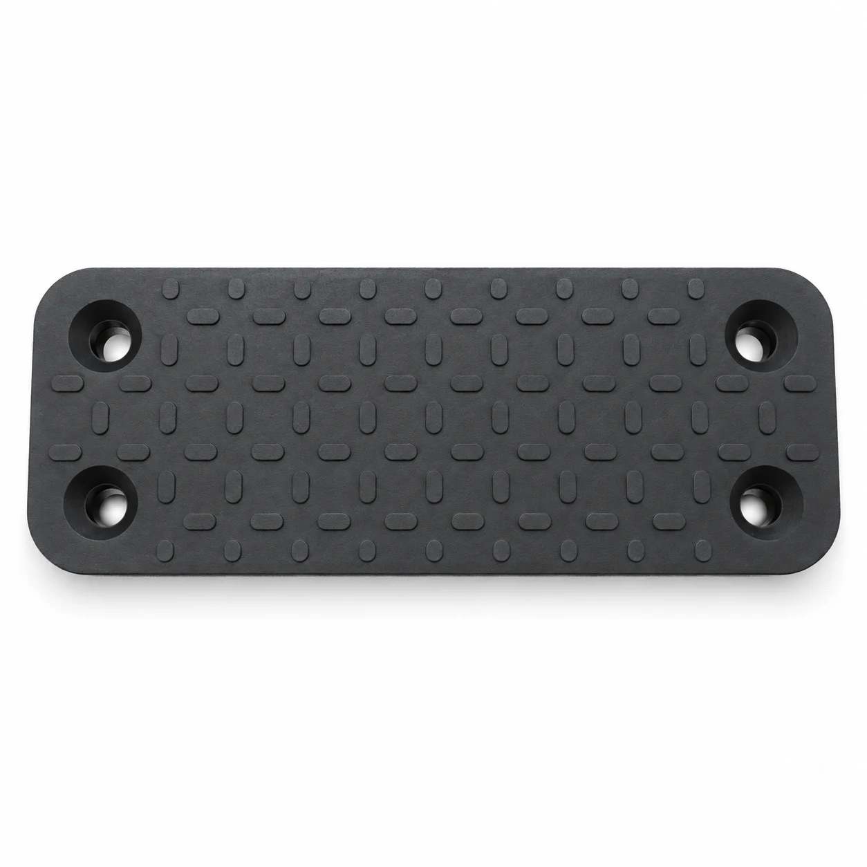
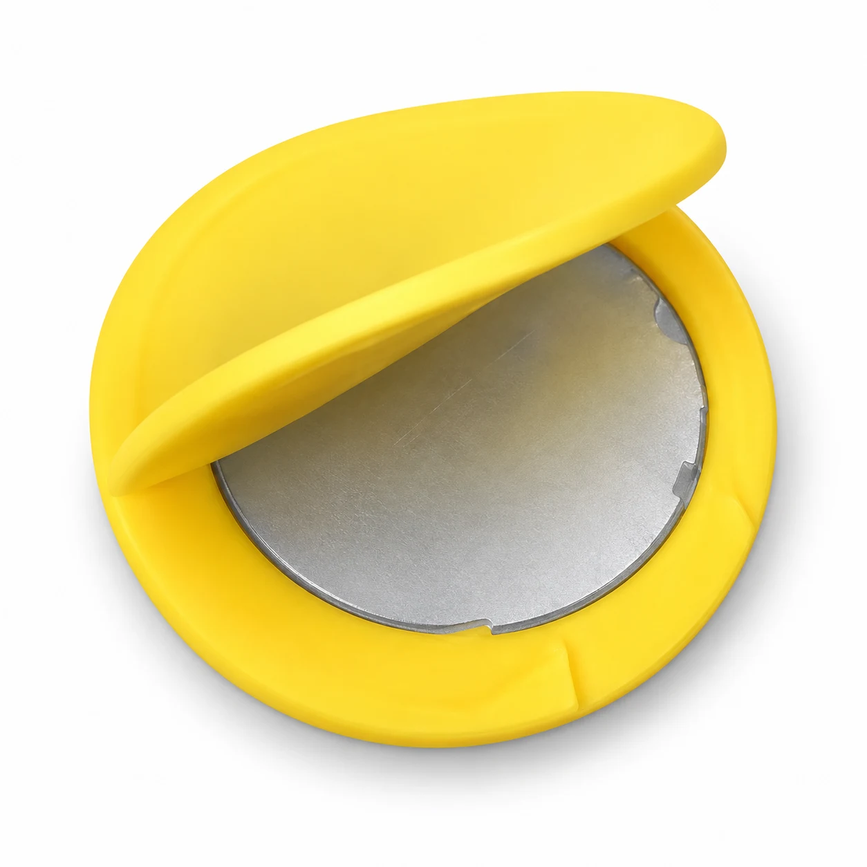
Round and rectangular bodies, colour options, partial coverage and separate protective covers support different installation needs. Coverage, insert position and exposed metal areas are defined on the drawing; colour alone does not identify the rubber formulation.
Geometry and Dimension Definition
Use functional datums and define the magnetization reference on the drawing. The table below provides the minimum geometry information for a practical manufacturing review.
| Parameter | How to define it | Why it matters |
|---|---|---|
| D / L × W | Overall coated footprint | Defines available contact and installation area |
| H — Overall height | Coated body plus boss or thread | Controls stand-off and clearance |
| Thread or stud | Size, engagement depth, material and position, including side fixings | Defines the mechanical interface |
| Rubber thickness | Nominal elastomer over the working face and edge | Balances protection, friction and magnetic air gap |
Design and Manufacturing Challenges
Balancing Rubber Thickness, Grip and Magnetic Gap
A thicker working-face layer provides more protection but increases the magnetic gap; an excessively thin layer is more vulnerable to tearing. We review the coated geometry, rubber flow and mould filling together to balance coverage, durability and holding performance. Gate layout, venting and part location help control local thin spots and trapped air.
Rubber can improve shear grip, but vertical holding still depends on the target surface, cleanliness and magnetic normal force. Rubber hardness, long-term creep and exposure to heat, UV, oil, salt and cleaning chemicals are part of material selection.
Choosing the Magnetization Sequence
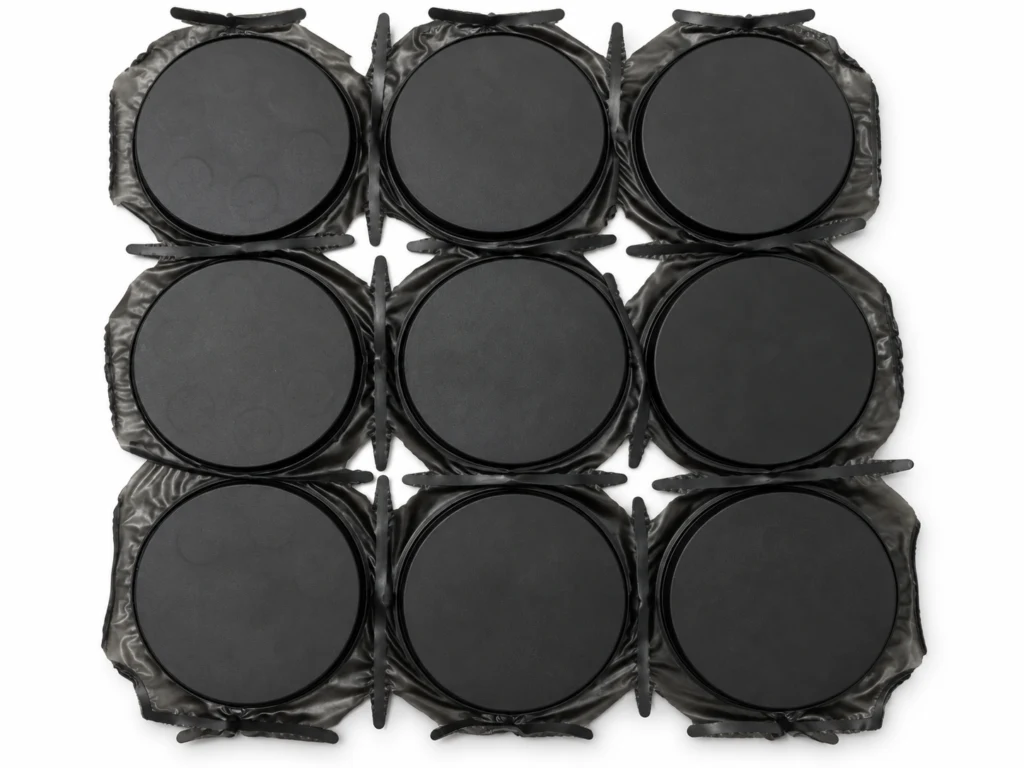
We use two manufacturing routes according to the magnetic layout and moulding conditions. The route is agreed before tooling so magnet grade, adhesive, rubber process and magnetizing fixture work together.
| Route | How it works | Process focus |
|---|---|---|
| Coat first, magnetize afterwards | The assembly is rubber coated before final magnetization, using a dedicated coil where needed for the specified multipole pattern. | Fixture geometry, pole layout and sufficient magnetizing field for the completed assembly. |
| Assemble magnetized parts, then coat | Pre-magnetized magnets are bonded to the steel carrier before rubber moulding. This can simplify the production sequence for suitable designs. | Magnet grade, adhesive stability and the temperature/time exposure during moulding to limit irreversible magnetic loss. |
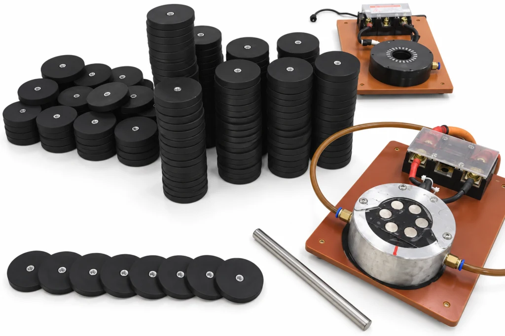
Large-Area Moulding and Bond Integrity
Large coated faces are more demanding to fill and bond consistently. Local thickness variation, bubbles and tearing require close control of component accuracy and mould fit. We coordinate the moulding process with a suitable heat-resistant adhesive system to support bonding across the larger area.
Our manufacturing experience includes large rubber coated assemblies used for equipment attachment on wind-tower structures. These projects connect magnetic performance with mechanical fixing, coating quality and the actual contact surface.
Project Example: 175 × 60 × 21 mm Assembly
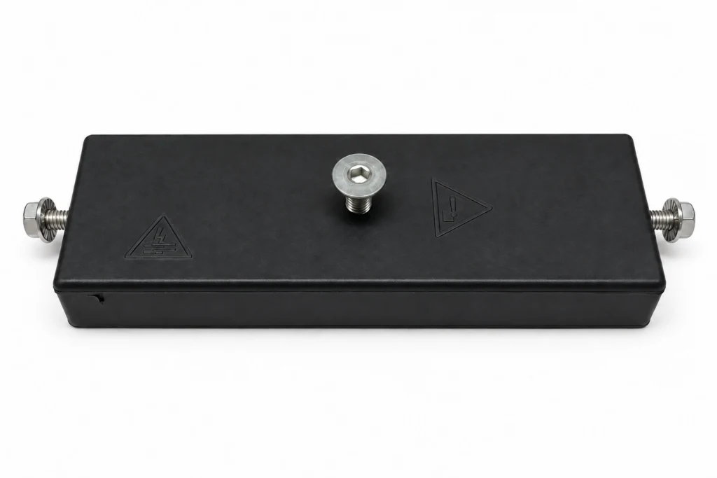
This example measures 175 × 60 × 21 mm and uses three fixing screws. The project reference reports a pull-off force of 445 kgf (approximately 4.36 kN). This is a product-specific pull-off figure, not a safe working load; the original test conditions must be confirmed before applying it to a new installation.
Quality Checks and Installation
- Check coated dimensions, working-face coverage, edge condition, flash removal and exposed fixing interfaces.
- Inspect for bubbles, cuts, pinholes or loss of adhesion that could compromise the protective layer.
- Verify the completed assembly using agreed magnetic or pull-force tests, including the target steel, gap and loading direction.
- Transfer mounting torque through the metal fixing structure, rather than through the rubber shell.
- Confirm environmental requirements for the complete assembly; rubber coverage alone does not establish a waterproof rating.
Typical Applications
Vehicle and marine accessories
Protective temporary mounts on coated steel, subject to validation of surface condition and exposure.
Sensors and cameras
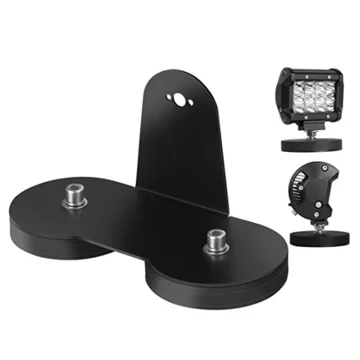
Repositionable sensor, camera and LED brackets on suitable steel surfaces, with a protective contact layer.
Signage and displays
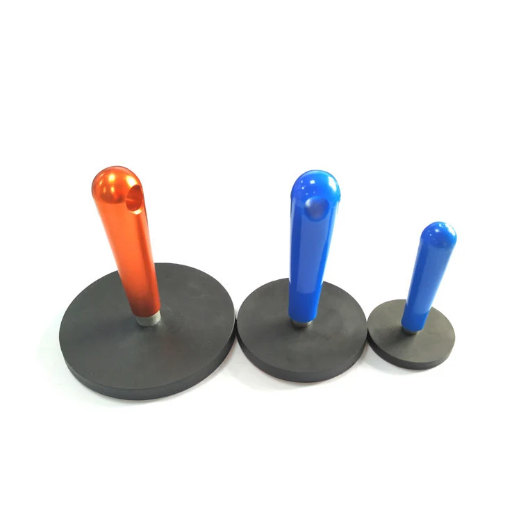
Protective attachment to finished metal panels.
Industrial cable management
Reusable anchors where drilling is not permitted.
Engineering Questions
Does rubber coating always increase holding force?
It can improve resistance to sliding, but the rubber layer creates a magnetic gap. Compare finished assemblies on the actual surface; direct pull and shear capacity are different measurements.
Which rubber material is best outdoors?
EPDM-like systems often suit weathering; nitrile suits oils. Actual formulation and temperature range must be confirmed.
Can the coating color be customized?
Selected colors are possible, subject to material, volume and UV requirements. Color should not be treated as the only material identifier.
How should the assembly be cleaned?
Use a compatible mild cleaner and inspect for cuts, swelling or exposed metal before reuse.
For a focused design review, share your drawing, fixing interfaces, rubber coverage and colour, operating temperature, target surface, pull and shear requirements, and prototype or annual quantities through our enquiry page. You can also return to Magnetic Assemblies for material-level guidance.