
Sintered NdFeB Magnets / Arc Magnets
Neodymium Arc Magnets for Motors, Rotors and Generators
Arc magnets follow the radius of a rotor or stator and are designed as part of a complete electromagnetic system. Radius, mechanical angle, axial length, air gap, pole arc and polarity sequence must be reviewed together.
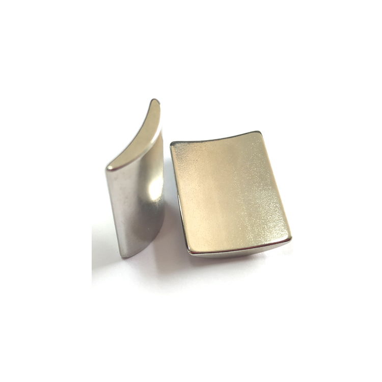
Geometry and Dimension Definition
Use functional datums and define the magnetization reference on the drawing. The table below provides the minimum geometry information for a practical manufacturing review.
| Parameter | How to define it | Why it matters |
|---|---|---|
| Ro / Ri | Outer and inner radius | Defines rotor fit, air-gap surface and radial thickness |
| L — Axial length | Length parallel to the motor shaft | Controls active motor length |
| α — Mechanical angle | Included angle of one arc segment | Determines segment count and circumferential gap |
| Chord / arc width | Reference width across the segment | Useful for inspection when linked to the radii and angle |
Design Considerations
Pole arc coefficient
The magnet arc relative to pole pitch influences back-EMF waveform, cogging torque and material utilization. It should be selected with electromagnetic simulation.
Air gap and radius matching
Small radius or thickness errors can change the working air gap. Matched-set inspection helps control rotor balance and field consistency.
Skew and segmentation
Skewed or multi-piece arrangements can reduce cogging and eddy losses, but increase assembly and polarity-control requirements.
Manufacturing and Assembly Notes
- Arc grinding requires dedicated tooling and reliable datums; radius, angle and thickness tolerances interact.
- Edges and corners are vulnerable during coating and automated insertion.
- Incorrect polarity or angular orientation can invalidate an assembled rotor, so fixtures and 100% polarity checks may be required.
- High-speed rotors need adhesive, sleeve retention, balance and temperature reviewed as one system.
Typical Applications
Servo and industrial motors
Matched arc sets for torque density and repeatable commutation.
EV auxiliary drives
High-coercivity grades and controlled rotor assembly for thermal stability.
Drone and high-speed motors
Thin air gaps, low rotor mass and careful mechanical retention.
Permanent-magnet generators
Custom radii and pole arcs for efficiency across the operating range.
Engineering Questions
How is the number of arc segments selected?
Segment count follows pole count, rotor diameter, magnetization feasibility, assembly process and electromagnetic targets. It should not be chosen from geometry alone.
Why do arc sets need matching?
Small differences in magnetic moment, radius and thickness can affect air gap, rotor balance and torque ripple. Lot and set control improve repeatability.
Should the arc be magnetized before or after assembly?
Both routes are possible. The choice depends on field strength, fixture access, assembly safety and magnetizing equipment.
When is a high-temperature grade needed?
Select grade from the worst-case magnet temperature, load line and demagnetizing field—not only ambient temperature. Motor transient conditions should be included.
For a focused design review, share your drawing, operating temperature, air gap, target magnetic performance and annual volume through our enquiry page. You can also return to Sintered NdFeB Magnets for material-level guidance.