
Applications / Pipeline Inspection & Pigging
Magnets for Pipeline Inspection Equipment
Custom magnetic assemblies for pipeline inspection and magnetic flux leakage (MFL) tools. Guande combines precision-machined magnet segments, No. 10 steel flux paths, stainless-steel support structures and complete-assembly magnetization to support consistent magnetic output and rigid integration.
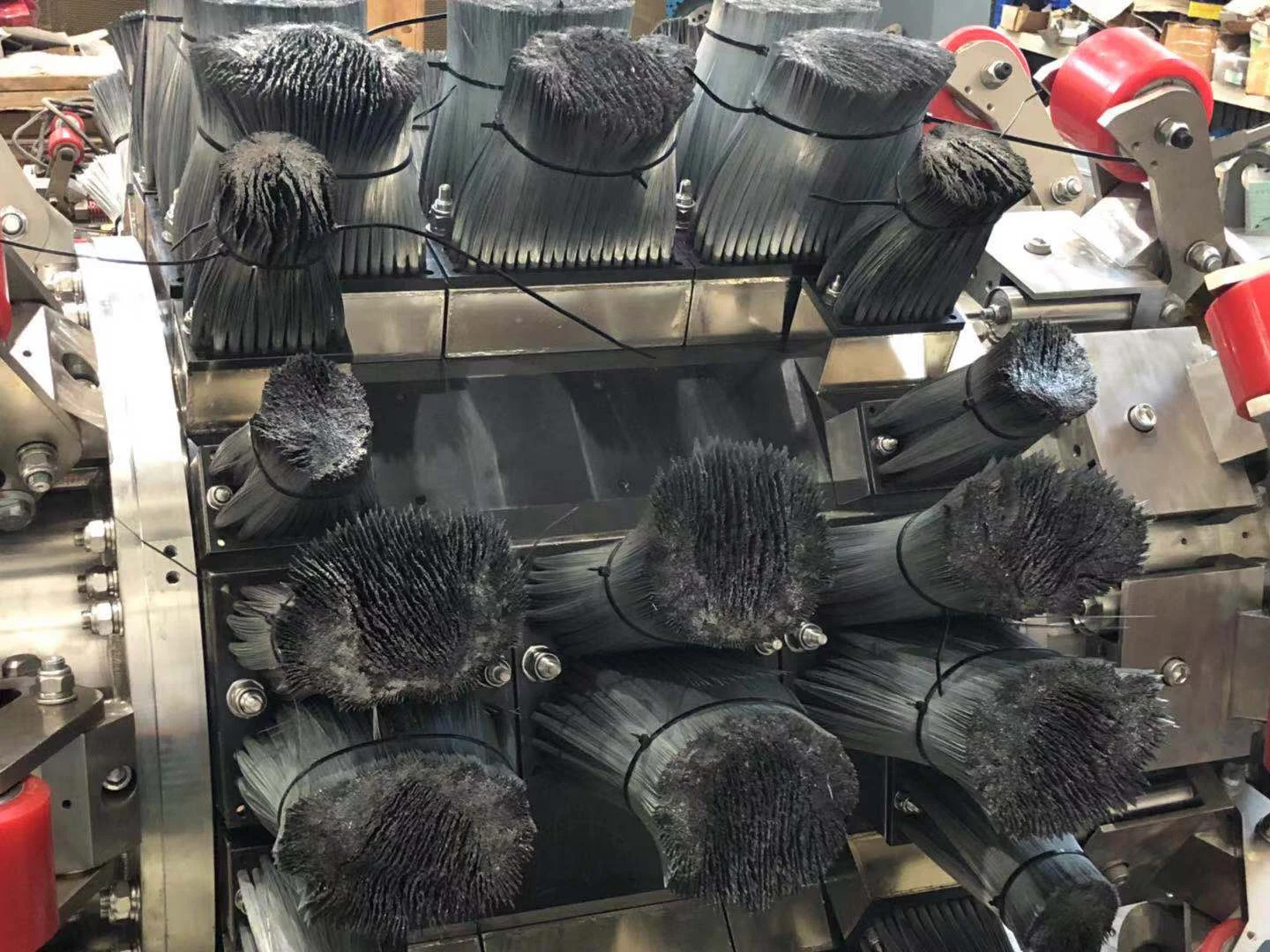
Product Overview
The magnetic module directs flux through a No. 10 low-carbon steel structure to the steel-brush interface. Magnetic performance and mechanical rigidity must be considered together: the assembly needs a controlled flux path, stable mounting and a structure suited to the inspection tool’s working conditions.
We manufacture these modules to the equipment drawing, coordinating magnet segmentation, mating surfaces, steel components, stainless-steel supports and the final magnetization process. The supply scope and brush interface are defined for each project.
Geometry and Specification Definition
Start with the complete module drawing and the required magnetic output. Large formats may involve a magnetic footprint around 200 mm in length and 100 mm in width or larger; the practical segmentation and magnetization route are reviewed for the specific geometry.
| Parameter | What to specify | Manufacturing focus |
|---|---|---|
| Assembly envelope | Length, width, height, datums and mounting holes | Segment layout, fit and installation clearance |
| Magnetic requirement | Polarity, field target, measurement position and working gap | Material selection and final magnetization |
| Segment interfaces | Joint positions, flatness and dimensional tolerances | Accurate mating faces and consistent assembly |
| Steel and support structure | No. 10 steel, stainless grade and brush attachment details | Flux path, rigidity and joining sequence |
| Operating conditions | Temperature, vibration, wear and exposure | Material, protection and retention review |
| Acceptance criteria | Dimensional checks and agreed magnetic test method | Repeatable prototype and production verification |
Core Manufacturing Challenges
Reliable output depends on how the complete module is made. Our processing approach addresses the four critical interfaces below.
1. Combining Magnetic Output with Structural Rigidity
The No. 10 steel component carries magnetic flux and supports the steel-brush interface. A strong magnet alone cannot compensate for an unsuitable flux path or an unstable structure. We review the steel geometry, magnet contact faces and mounting features together so the module can meet both magnetic and mechanical requirements.
2. Precision Segmentation for Large Magnetic Blocks
Large magnetic bases can require multiple magnet pieces rather than a single block. Segment dimensions and face flatness influence joint fit and the consistency of the finished magnetic assembly. We focus on precision machining of the mating surfaces, controlled positioning and inspection of the assembled geometry before final magnetization.
Segmentation is assessed alongside material consistency and the ability to magnetize the complete structure. Tolerances are agreed from the drawing and functional requirements, rather than applying one tolerance to every large-format design.
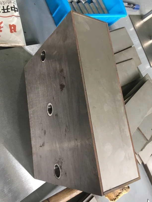
3. Joining No. 10 Steel and Stainless Steel
The stainless-steel perimeter supports the overall assembly, while the low-carbon steel provides the intended magnetic path. Joining these different materials requires careful control of the welding sequence, fixture support, heat input and distortion. Our process review connects weld construction with the final dimensions and the protection of the magnetic components.
4. Magnetizing the Complete Assembly
The finished module is magnetized as a complete unit. Large assemblies place demanding requirements on magnetizing energy, fixture geometry and field direction. We plan the high-energy magnetization step around the assembled magnetic circuit, then verify polarity and magnetic output against the agreed test conditions.
Manufacturing and Quality Control
- Drawing review: define the magnetic target, segment arrangement, material grades and critical interfaces.
- Precision processing: machine magnet segments and steel parts with attention to mating-face flatness and dimensional fit.
- Controlled assembly: align segments, build the support structure and check mounting datums after joining.
- Final magnetization: match the fixture and magnetizing process to the complete module.
- Agreed verification: check critical dimensions, polarity and field measurements at defined locations before delivery.
Typical Applications
Magnetic modules for oil and gas pipeline inspection equipment, MFL inspection tools and custom inspection pig magnetizers. Module layout, pole geometry and brush interfaces are adapted to the equipment design. Inspection performance must be validated in the complete tool under its actual operating conditions.
Engineering Questions
Can you manufacture a large module from multiple magnet segments?
Yes. We review the footprint, segment layout, material and final magnetization route together. Accurate dimensions and flat mating surfaces are central to achieving consistent assembly.
Can you integrate low-carbon steel and stainless-steel supports?
Yes. The No. 10 steel flux path and stainless-steel support structure can be processed as part of the module. Stainless grade, weld arrangement and critical dimensions are confirmed from the drawing.
Do you magnetize the module after assembly?
The construction described here uses final magnetization of the complete assembly. Feasibility depends on the magnetic circuit, dimensions and magnetizing fixture, which are reviewed before production.
What information is needed for a quotation?
Please provide the assembly drawing or sample, pipe and tool dimensions, brush and mounting interfaces, operating temperature, target field and test gap, material or coating requirements, and prototype or annual quantities.
Send your drawing and operating requirements through our enquiry page for a manufacturing review. Explore custom magnetic assemblies or return to Applications for other equipment needs.