A magnetic coupling transmits rotary motion and torque from one shaft to another through a magnetic field rather than direct mechanical contact. The driving and driven members can therefore be separated by an air gap or a stationary containment barrier. This contactless arrangement is especially valuable when a conventional shaft seal would create a leakage, contamination, wear, or maintenance risk.
Key takeaway: a magnetic coupling is not simply two magnets facing each other. Reliable torque transmission depends on the pole arrangement, working radius, air gap, containment barrier, magnetic return path, temperature, speed, alignment, and the application’s required safety margin.
1. What Is a Magnetic Coupling?
In a typical permanent magnetic coupling, one magnetic rotor is connected to the motor or driving shaft and a second rotor is connected to the load. Alternating north and south poles are arranged around both rotors. When the driver rotates, the magnetic field attempts to keep the driven pole pattern aligned, so the output rotor follows without physical contact between the two magnetic members.
Because torque crosses the gap magnetically, a nonmagnetic wall can be placed between the rotors. In sealed pumps, mixers, and process equipment, this wall isolates the process fluid from the motor side and removes the dynamic shaft penetration that normally requires a mechanical seal.
2. Core Working Principle
The working principle is the attraction and repulsion between synchronized multipole magnetic fields. At no load, opposite poles tend to align in the lowest-energy position. When load torque is applied, the driven rotor lags behind the driving rotor by a small angular displacement. This torque angle creates a tangential magnetic force that transfers torque to the output shaft.
For a synchronous permanent magnetic coupling, transmitted torque rises with the torque angle until it reaches a peak or pull-out torque. If the load exceeds this limit, the rotors slip out of magnetic synchronism instead of transmitting unlimited mechanical force. This behavior can provide overload protection, although repeated slipping may create heat and should not be treated as a normal operating condition.
The available torque is influenced by:
- magnet grade, remanence, coercivity, and operating temperature;
- number of poles, pole arc, magnet thickness, and magnetization direction;
- effective rotor radius and axial engagement length;
- radial or axial air gap, including the containment-wall thickness;
- back-iron thickness, permeability, and magnetic saturation;
- assembly tolerances, concentricity, runout, and angular positioning;
- conductivity of the containment can and resulting eddy-current losses at speed.
Small increases in the magnetic gap can cause a significant reduction in torque. The design should therefore be evaluated as a complete magnetic circuit rather than by comparing magnet surface gauss alone.
3. Main Structural Components
Driving rotor
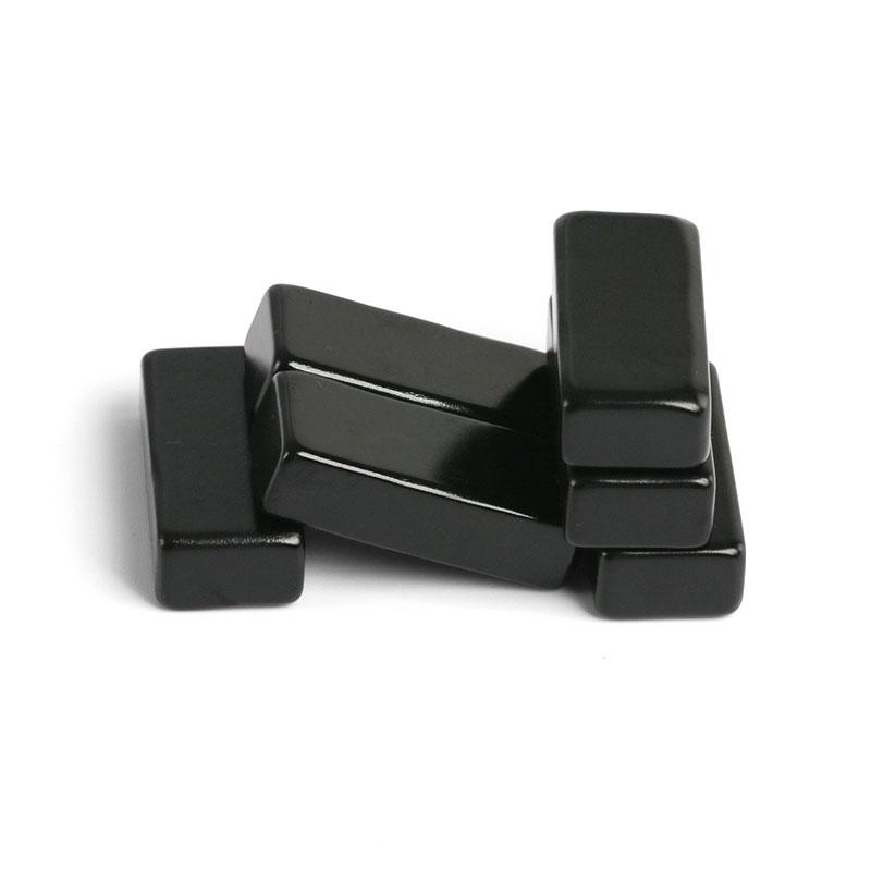
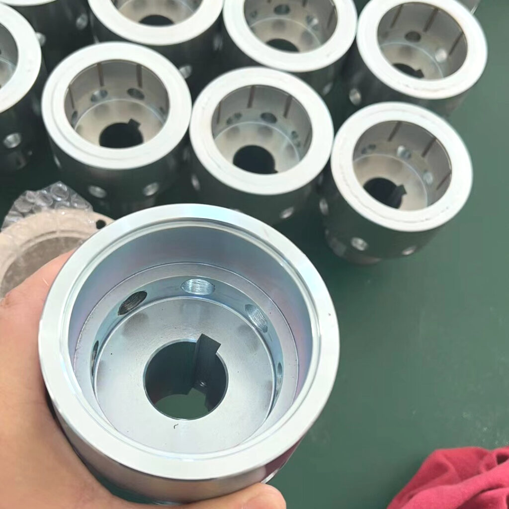
The outer or input rotor is attached to the motor shaft. It carries an alternating array of permanent magnets and normally includes a ferromagnetic yoke that provides a low-reluctance return path and supports the magnets mechanically.
Driven rotor
The inner or output rotor is connected to the pump impeller, mixer, instrument shaft, or other load. Its pole pattern is matched to the driver so that the two rotors develop synchronous torque.
Permanent magnets
NdFeB is widely used where compact size and high torque density are required. SmCo may be selected for higher operating temperatures, improved thermal stability, or demanding corrosive environments. Grade selection must consider both temperature and the local demagnetizing field during overload.
Back iron and rotor bodies
Steel yokes concentrate flux and reduce leakage. Stainless steel, aluminum, engineering plastics, and other materials may be used for structural parts, depending on strength, corrosion, mass, and magnetic requirements.
Containment can or isolation barrier
This stationary, nonmagnetic component separates the process side from the drive side. Its material and thickness affect pressure capability, chemical compatibility, heat generation, and magnetic gap. Metallic cans can produce eddy-current losses; high-resistivity alloys, ceramics, or engineered polymers may reduce those losses when suitable for the pressure and temperature.
Hubs, shafts, bearings, and retention features
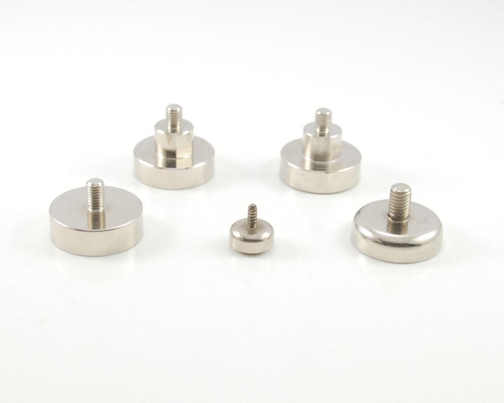
Keyways, splines, clamping hubs, threaded connections, adhesives, sleeves, and mechanical retainers transfer torque within each rotor and prevent magnet movement at speed. Bearings and shaft interfaces must maintain the designed gap under radial load, thermal growth, and vibration.
4. Main Types and Their Characteristics
| Type | Configuration | Main characteristics |
|---|---|---|
| Coaxial permanent magnetic coupling | Inner and outer cylindrical rotors | High torque density, compact radial arrangement, common in sealed pumps and mixers. |
| Axial-face or disc coupling | Two magnetic discs face each other | Simple axial assembly, adjustable gap, useful where radial packaging space is limited. |
| Permanent magnetic synchronous coupling | Matched permanent-magnet pole sets | No steady-state slip, precise speed ratio, overload disengagement at pull-out torque. |
| Eddy-current magnetic coupling | Permanent-magnet rotor coupled to a conductive rotor | Operates with slip, provides soft starting and vibration isolation, but generates heat in the conductor. |
| Linear magnetic coupling | Magnetic elements arranged along a linear path | Transfers push-pull motion through a sealed wall for actuators, valves, and instruments. |
The term “magnetic coupling” may describe several operating principles. A synchronous permanent magnetic coupling is normally chosen for accurate, contactless torque transfer, while an eddy-current coupling is chosen when controlled slip and soft engagement are useful.
5. Major Application Scenarios
- Sealless pumps: chemical, pharmaceutical, semiconductor, water-treatment, and laboratory pumps handling hazardous, corrosive, high-purity, or valuable fluids.
- Mixers and agitators: hygienic or sealed vessels where shaft seals could leak or introduce contamination.
- Vacuum and pressure equipment: torque transfer through a chamber wall without a rotating feedthrough.
- Food and medical systems: isolated drives that support cleaning, hygiene, and reduced lubricant migration.
- Underwater and enclosed equipment: drive transmission across a waterproof housing.
- Instrumentation and meters: low-torque motion transfer for indicators, counters, valves, and sensors.
- Robotics and automation: contactless actuation, overload release, easy module separation, and reduced wear.
6. How to Select a Magnetic Coupling
A useful specification begins with continuous torque, peak starting torque, speed, duty cycle, and acceptable slip behavior. The designer should also define the maximum radial and axial envelope, shaft interfaces, available air gap, containment-can material and thickness, pressure, temperature, fluid chemistry, and cleaning requirements.
For high-speed designs, eddy-current heating, centrifugal retention, rotor balance, and bearing deflection become critical. For high-temperature service, the magnet’s irreversible flux loss and the adhesive or encapsulant temperature rating must be checked. Corrosive media require a complete review of magnet coating, containment materials, welds, and possible fluid ingress—not just a higher-grade magnet.
7. Common Engineering Risks
- specifying only nominal torque without starting, upset, or jam conditions;
- underestimating the total magnetic gap after adding coating, clearance, and containment-wall tolerances;
- using a conductive containment can without evaluating speed-dependent heat;
- allowing steel fasteners or nearby structures to short-circuit the magnetic field;
- selecting an NdFeB grade by room-temperature pull force while ignoring operating temperature;
- relying on adhesive alone without considering centrifugal force and long-term environmental exposure;
- omitting concentricity, runout, balance, and pole-position tolerances from the drawing.
8. Our Design, Assembly, and Testing Capabilities
Guande Magnet supports magnetic coupling development from an initial torque and envelope requirement through prototype validation and repeatable production. Our engineering review covers magnetic-circuit layout, pole count, magnet grade, magnetization direction, back-iron saturation, gap sensitivity, containment-wall influence, temperature margin, and manufacturing tolerances.
For custom assemblies, we can support machined hubs and yokes, magnet sorting and polarity control, dedicated positioning fixtures, adhesive and encapsulation selection, mechanical retention, and controlled assembly sequences. Fixtures are designed to manage magnetic attraction safely while maintaining pole pitch, concentricity, axial position, and adhesive bond-line requirements.
Inspection can include magnet dimensions and coating, magnetic properties, pole sequence, surface field or flux, assembly runout, concentricity, static torque or pull-out torque, dynamic rotation checks, and visual inspection. Depending on the project, additional verification can include balance, temperature cycling, corrosion testing, pressure or leak testing of the customer’s containment design, and lot traceability.
Early design cooperation is especially valuable because magnetic performance, mechanical strength, heat, corrosion resistance, and assembly cost are closely linked. A small change to the air gap or rotor diameter can have a greater impact than simply selecting a stronger magnet grade.
Frequently Asked Questions
Can a magnetic coupling replace every mechanical coupling?
No. Magnetic couplings are most valuable when sealing, isolation, overload release, or low wear justifies the additional magnetic design. A direct mechanical coupling may remain more economical when there is no barrier and very high torque must be transferred in a small space.
What happens when the load torque is too high?
A synchronous permanent magnetic coupling can lose synchronism and slip when the pull-out torque is exceeded. The drive should be stopped or unloaded promptly because repeated pole slipping can produce impact, vibration, and heat.
Does the containment can weaken the coupling?
The can increases the magnetic gap, which reduces torque. A conductive metal can may also generate eddy-current heat at speed. Its thickness and material must therefore be included in the magnetic and thermal calculations from the beginning.
For a custom magnetic coupling review, send us your continuous and peak torque, speed, temperature, available space, shaft details, containment barrier, and operating environment. We can help translate the application requirements into a practical magnet, rotor, assembly, and inspection plan.