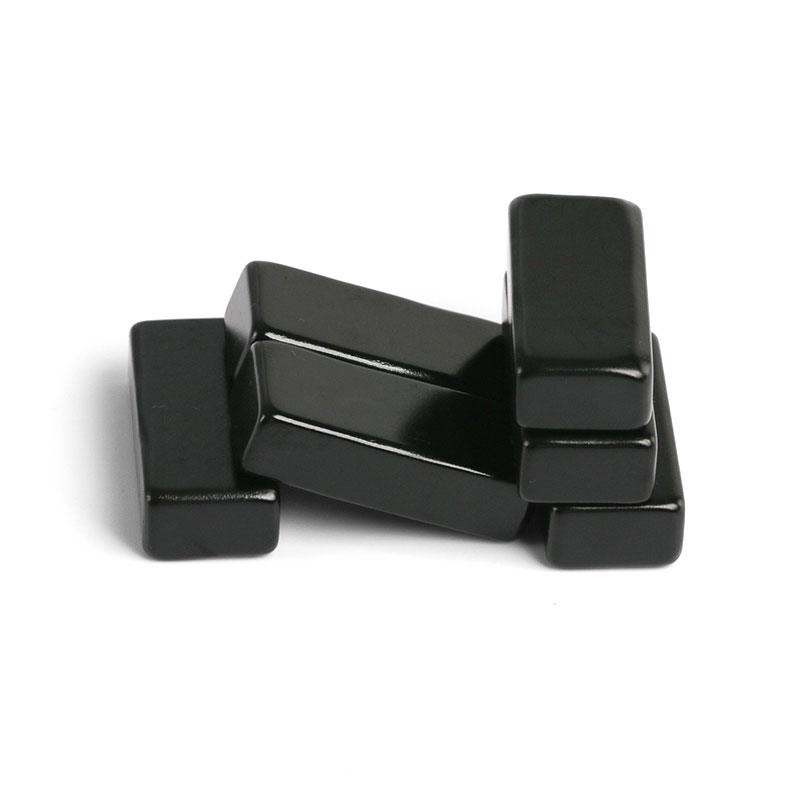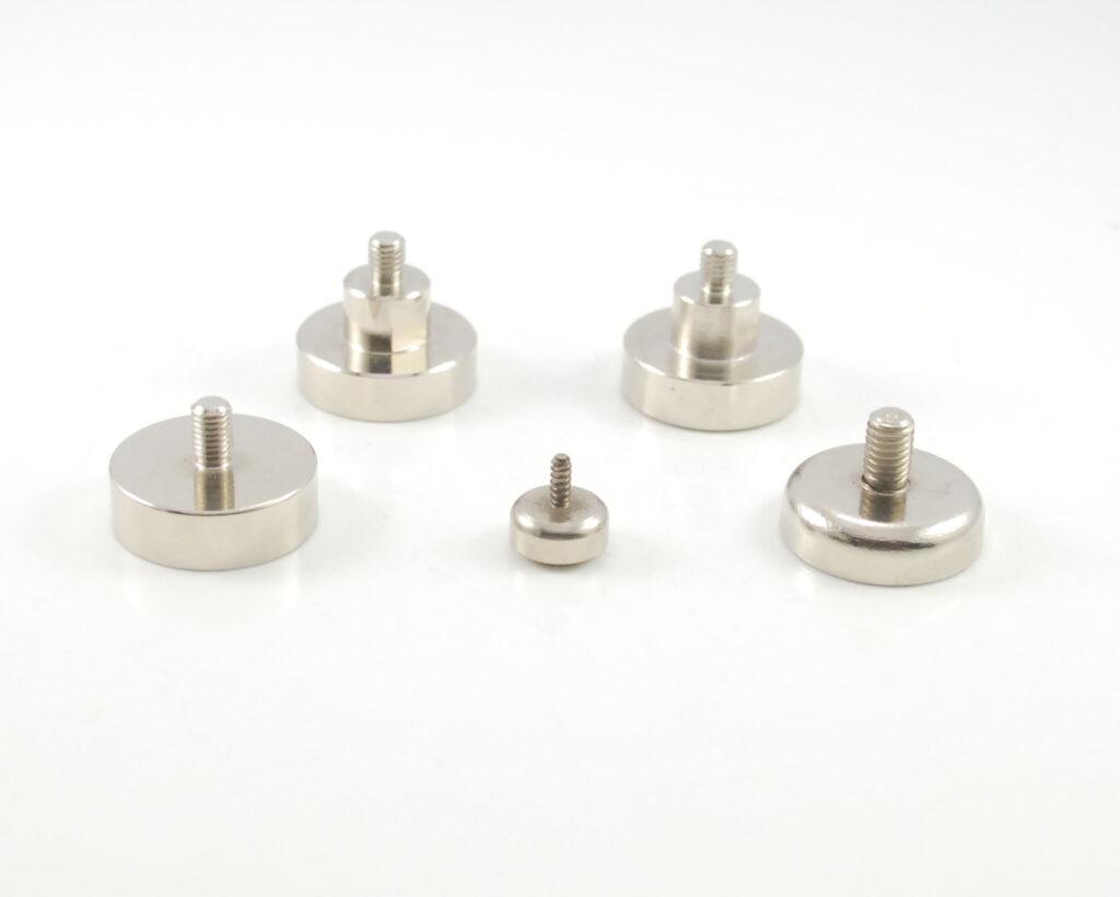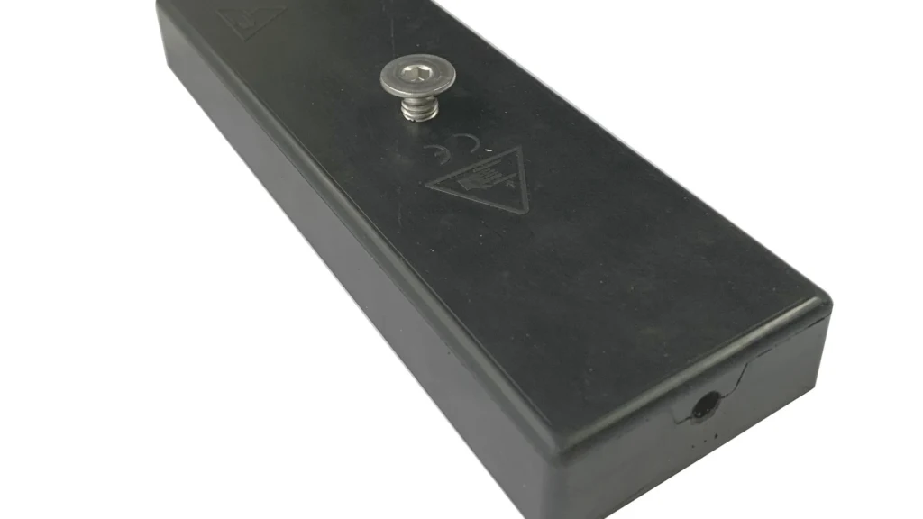
A rubber-coated magnet is not simply a finished magnet dipped in rubber. A production part may combine several NdFeB magnets, a low-carbon-steel flux plate, threaded hardware and a molded TPE, TPU, EPDM or silicone cover. The mold must hold these inserts against magnetic and injection forces while controlling cover thickness, flash, sealing, flatness and cosmetic appearance.
Manufacturing rule: define the magnetic circuit, elastomer, molding route and magnetization sequence before releasing the tool. Changing any one of them later can alter cavity dimensions, fixtures, cycle time and final pull force.
Choose the Molding Route First
TPE and TPU covers are commonly made by insert injection molding. The inserts are located in the cavity, molten material flows around them, and the molded part cools before ejection. Vulcanized EPDM, NBR or silicone may use compression, transfer or liquid-injection molding, depending on compound and geometry. Each route needs different gates, vents, shrinkage allowances, mold temperature and cure or cooling time.
The elastomer selection should start with service requirements: temperature, outdoor exposure, oil or chemical contact, hardness, friction, compression set, color and adhesion. A soft high-friction compound may resist sliding well but deform under clamp load. A harder TPU may provide better wear resistance but transmit more impact to the magnet assembly.
Mold Material: Life, Cost and Production Efficiency
Tool life depends on more than the steel name. Hardness, heat treatment, cavity finish, gate erosion, compound additives, part geometry, maintenance and molding pressure all matter. The figures below are indicative planning ranges, not guaranteed shot counts.
| Mold material | Indicative production role | Relative tool cost | Life and efficiency considerations |
|---|---|---|---|
| 7075 aluminum | Prototype and low-volume validation | Lowest; fast machining | Shorter life; easy changes; limited wear and pressure margin |
| P20 / 718H pre-hardened steel | General production with non-abrasive compounds | Baseline to medium | Good machinability and repairability; often suitable for moderate volumes |
| H13 hardened tool steel | High pressure, hot tooling, wear-prone inserts and long runs | Higher machining and heat-treatment cost | Strong wear and thermal-fatigue resistance; longer lead time |
| S136 / 420 stainless mold steel | Corrosive compounds, high-polish faces and demanding surface quality | High | Good corrosion resistance and polish retention; disciplined heat treatment required |
| Hybrid tool | P20 base with hardened gates, shutoffs or replaceable cavity inserts | Targeted investment | Balances cost and wear; damaged high-risk areas can be replaced |
For a prototype, aluminum can shorten lead time and reveal fill, venting and shrinkage problems before production steel is cut. For stable high-volume demand, multi-cavity hardened tooling normally reduces unit cost, but only if cavity balance and insert loading are reliable. A four-cavity mold that requires slow manual alignment may deliver less output than a well-automated two-cavity mold.
Designing the Mold Around Magnetic Inserts
The insert nest must establish position without point-loading the brittle magnets. Steel plates, threaded bushes and magnets require independent datums so accumulated tolerance does not shift the rubber skin. Shutoff areas need enough land to prevent flash while avoiding damage to coatings and plated hardware.
Gate location should allow the flow front to sweep air toward vents rather than trap it behind the insert. Balanced runners reduce cavity-to-cavity variation. Replaceable gate and vent inserts make maintenance easier, and cooling channels should be symmetrical around the working face to limit differential shrinkage. For high output, poka-yoke features, loading trays or a robot gripper should prevent reversed inserts and missed hardware.
Magnetize Before Molding or After Molding?
| Sequence | Advantages | Risks | Best-fit situations |
|---|---|---|---|
| Magnetize first, then overmold | Magnetic performance can be checked before molding; useful when the completed assembly is difficult to magnetize | Attraction to the tool, debris and other inserts; harder loading; molding heat can cause irreversible loss | Low-temperature process, high-coercivity grade, simple controlled fixtures, or no feasible post-mold magnetizing fixture |
| Overmold first, then magnetize | Nonmagnetic inserts are easier to load; less contamination and magnetic force; avoids pre-magnetized heat loss | Pulse must reach saturation through rubber and steel; fixture cost; finished geometry may limit field direction | Higher-volume automation, multipole assemblies and processes with demanding thermal cycles |
Pre-magnetized inserts need positive mechanical retention because injection pressure can move them even when magnetic attraction appears to hold them. Ferromagnetic tool components can also pull the insert away from its datum. Nonmagnetic fixture inserts may reduce attraction, but they must tolerate pressure and temperature.
Post-mold magnetization is often cleaner for mass production, yet it must be proven with the complete magnetic circuit. Steel backing can shunt the pulse, and a thick assembly may require more magnetizing voltage and a specialized coil. The magnet grade, pole pattern and fixture should be validated by pole mapping or flux measurement—not only by checking that the part attracts steel.
How to Prevent Bubbles and Voids
Bubbles can come from moisture, trapped air, volatile primer, incomplete packing, excessive melt temperature or gas released from contaminated inserts. Hygroscopic TPU and some TPE grades must be dried to the material supplier’s specification and transferred in a closed system. Magnets and steel inserts should be clean, dry and at a controlled temperature before loading.
Vents belong at the last-fill locations, weld lines and behind deep ribs. Vent depth must match the specific compound: too shallow traps air, while too deep produces flash. Vacuum assistance can help on large flat covers or complex insert packages. Gate size, injection speed and switchover should be tuned so the cavity fills without jetting or burning. Increasing pressure alone rarely fixes a venting problem.
If a primer or bonding agent is used, its film thickness and flash-off time must be controlled. Wet solvent can gas during molding. For a purely mechanical encapsulation, grooves, holes or undercuts can provide interlock without relying on chemical adhesion, but these features must not create a weak tear line in the rubber.
How to Control Flatness and Surface Quality
Large flat rubber coated magnets are sensitive to nonuniform wall thickness and asymmetric cooling. The mold should keep the cosmetic working face against a stable cavity surface, distribute gates symmetrically and cool both sides at a controlled rate. Thick local bosses should be cored where possible, and the steel insert should be flat before molding.
Pack pressure, cooling or cure time, mold temperature and ejection timing should be recorded as a process window. Ejecting early can bend a hot part; excessive pack pressure can distort inserts or raise flash. Flatness should be measured after a defined conditioning time at a controlled temperature, using a fixture that does not compress the rubber. A vision system or scanning gauge can monitor edge roll, sink, flash and surface contamination during batch production.
Rubber Thickness Changes the Magnetic Field
Rubber is effectively a nonmagnetic spacer. Every additional millimeter increases the working air gap between the magnet poles and the target steel, so flux density and normal pull force decrease. The reduction is nonlinear and depends on magnet size, pole spacing, steel thickness and circuit saturation. In a simplified contact model, force is proportional to approximately B², so a 20% decrease in working-face flux density can correspond to roughly a 36% force reduction.
| Indicative cover thickness | Magnetic effect | Mechanical benefit | Typical design use |
|---|---|---|---|
| 0.3–0.8 mm | Lowest added gap; strongest normal pull | Limited impact and wear margin | Compact parts with controlled smooth targets |
| 0.8–1.5 mm | Moderate pull reduction | Balanced surface protection and friction | General mounting products |
| 1.5–3.0 mm | Significant gap penalty | Better cushioning and abrasion allowance | Rough or sensitive painted surfaces |
| Above 3 mm | Often requires larger magnets or tighter pole pitch | High compliance and protection | Special impact, sealing or isolation requirements |
These ranges are starting points only. Rubber can still improve vertical holding because shear resistance is approximately the normal force multiplied by the friction coefficient. A bare plated magnet may have higher pull force but slide sooner on a vertical painted panel. The correct thickness is therefore chosen from both perpendicular pull and shear-load tests at the real surface condition.
From Prototype to Stable Batch Production
A controlled launch normally includes DFM review, mold-flow or fill analysis where useful, prototype tooling, material trials, first-article dimensional and magnetic inspection, process-capability sampling and a defined maintenance plan. Critical records include insert lot, magnet grade, magnetization status, rubber batch, drying condition, molding parameters, cavity number and pull-force result.
Guande develops each rubber coated magnet mount as a complete custom magnetic assembly. We review the NdFeB grade, steel flux path, hardware, elastomer, moldability, magnetic orientation, pull force and shear behavior. See our earlier guide to rubber-coated magnet design principles, our sintered NdFeB capabilities, and the related discussion of the NdFeB coating process.
For a new rubber coated neodymium magnet, send the assembly drawing, target steel, load direction, required force, temperature, chemical exposure, annual volume and preferred elastomer through our engineering quote form. We can compare the tooling and magnetization routes before production steel is released.