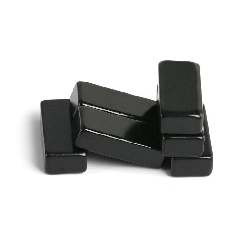
A bare disc magnet produces useful flux from both pole faces. In many holding applications, however, only one face is connected to the steel target. A one-sided magnetic assembly uses ferromagnetic steel to redirect the rear-side flux toward the working face. The result can be a much higher useful holding force within the same external envelope.
Key takeaway: a one-sided design does not create extra magnetic energy. It reduces leakage, provides a low-reluctance return path, and concentrates more of the available flux where the load is applied.
What Is a One-Sided Magnet?
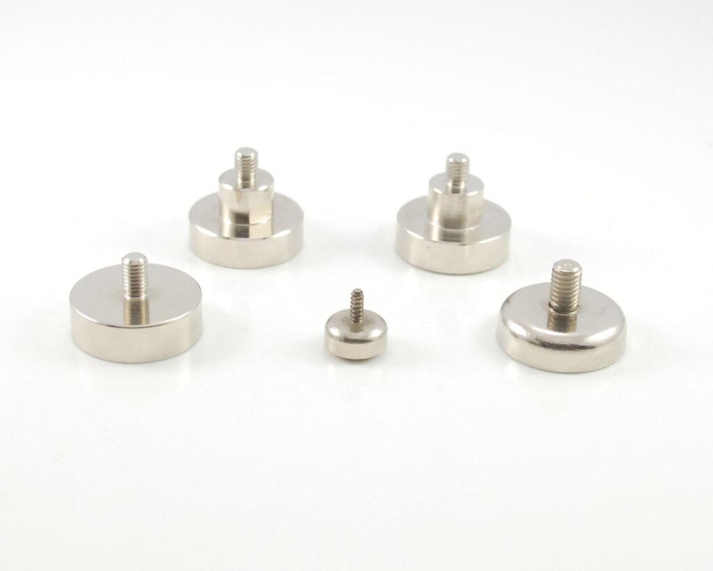
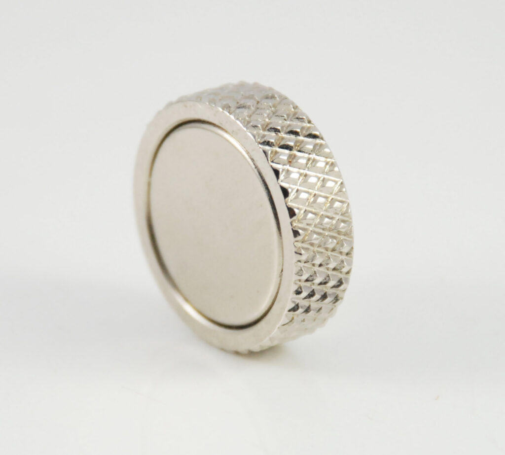
The term usually describes a magnetic circuit in which most of the external field is presented on one working surface. A common example is a pot magnet: an NdFeB disc or ring is installed inside a low-carbon-steel cup. The cup contacts one pole on the back and around the side, routes flux through the steel, and presents that return pole near the front perimeter. The exposed magnet face forms the other pole.
When the assembly touches a sufficiently thick steel plate, the target closes the magnetic circuit between the center pole and the surrounding steel rim. Flux crosses a short working gap and the magnetic pressure creates strong normal attraction.
Why the Holding Force Increases
1. Rear-side flux is redirected to the useful surface
Without a yoke, part of the magnetic field spreads through air behind and around the magnet. Air has much higher magnetic reluctance than steel. A properly sized cup gives that flux an easier return path and guides it toward the contact face instead of allowing it to leak into unused space.
2. Opposite poles appear close together at the working face
The exposed magnet and the steel rim form adjacent poles. A steel target bridges the two poles across a very short path. This compact loop produces a high local flux density at the interface, particularly when the mating plate is flat, clean, and thick enough to avoid saturation.
3. The pole area and field distribution are optimized
Holding force is related to the magnetic flux density over the effective contact area. The steel pole geometry can spread or concentrate the flux so that more of the target area contributes. Cup wall thickness, rim width, magnet diameter, recess depth, and any center pole are designed together.
4. The circuit shields part of the stray field
The steel cup provides partial magnetic shielding on the back and sides. This does not make the assembly field-free, but it can reduce unwanted interaction with adjacent hardware while improving the front-to-back field ratio.
Why the Improvement Is Not Unlimited
A steel cup can only carry a finite amount of flux. If the wall or pole piece saturates, using a higher-grade magnet or adding more magnet volume produces less benefit than expected. The target plate can also saturate, especially when it is thin. After saturation, additional magnet strength mostly increases leakage.
The quoted pull force is normally measured perpendicular to a thick, polished, low-carbon-steel plate under ideal contact. Real installations include paint, zinc, rust, adhesive, rubber, curvature, surface roughness, and misalignment. Each nonmagnetic layer increases the effective air gap, and holding force can fall rapidly.
The Role of the Air Gap
Air-gap control is often more important than moving from one NdFeB grade to another. Even a thin coating or protective pad can significantly reduce flux at the target. A rubber boot improves friction and protects the surface, but the magnetic circuit must compensate for its thickness.
For this reason, a pull-force specification should include the target material, target thickness, surface finish, coating, test direction, contact area, and safety factor. Comparing catalog values from different test methods can be misleading.
Pull Force Is Not the Same as Shear Holding
Normal pull force acts perpendicular to the plate. A vertical load usually tries to slide the assembly, so the capacity depends on friction as well as magnetic preload. A smooth nickel-plated pot magnet can have excellent direct pull force but limited shear resistance. Rubber coating, a textured pad, mechanical stops, or multiple magnets may be required.
Dynamic loads, vibration, peel, impact, and an off-center moment can reduce usable capacity further. Design safety should be based on the worst load direction rather than a single static pull number.
Common One-Sided Magnetic Structures
- Pot magnet: a round magnet inside a steel cup, with a threaded hole, stud, countersunk hole, or internal thread.
- Channel magnet: a rectangular magnet or magnet set inside a U-shaped steel channel.
- Sandwich assembly: a magnet positioned between steel pole pieces to create two working poles.
- Rubber-coated system: multiple magnets and a steel carrier encapsulated in elastomer for friction and surface protection.
- Custom magnetic chuck: a machined pole pattern designed for a specific workpiece geometry and release method.
Design Variables That Control Performance
| Variable | Why it matters |
|---|---|
| Magnet grade and volume | Set the available magnetomotive force and temperature margin. |
| Cup and pole-piece steel | Determine reluctance and saturation behavior. |
| Rim width and wall thickness | Control flux distribution and structural strength. |
| Working gap | Paint, rubber, adhesive, and roughness can sharply reduce force. |
| Target plate | Material, thickness, size, and curvature affect circuit closure. |
| Temperature | Changes magnet output and possible demagnetization margin. |
| Load direction | Direct pull, shear, peel, and torque require different safety factors. |
When a Bare Magnet May Be Better
A one-sided assembly adds steel, size, mass, and manufacturing steps. A bare magnet may be preferable when both faces are used, the field must extend farther into space, weight is critical, or the magnet is integrated into an existing steel circuit. The correct comparison is between complete assemblies under the same gap and target conditions.
Frequently Asked Questions
Does a steel cup double the magnetic force?
Not by a fixed ratio. The improvement depends on the original leakage, magnet geometry, steel saturation, target plate, and air gap. Some well-optimized assemblies show a large gain, while a poorly sized cup may add little.
Can stainless steel be used for the cup?
Many stainless grades are weakly magnetic or essentially nonmagnetic and are poor flux conductors. Low-carbon steel is common for the magnetic path, while corrosion protection is added by plating, coating, or an outer housing.
Why is the magnet sometimes recessed below the cup rim?
A recess protects the brittle magnet and can shape the contact poles, but it also creates an air gap. The recess depth must be optimized rather than chosen only for mechanical protection.
Guande Magnet designs pot magnets, channel assemblies, rubber-coated systems, and custom one-sided magnetic circuits. Share the target steel, working gap, load direction, required force, envelope, and temperature for a circuit review.