NdFeB magnets are famous for delivering very high magnetic strength from a compact volume, but they are also hard, brittle materials that can chip, crack, or fracture when subjected to impact, bending, or concentrated assembly loads. This is not a manufacturing defect by itself. It is a direct consequence of the sintered magnet’s material structure and the way permanent magnets are processed.
Key takeaway: NdFeB should be treated more like a technical ceramic than a piece of steel. It performs well under properly distributed compression, but it does not tolerate impact, tension, bending, or point loading.
Why NdFeB Magnets Are Brittle
Most high-performance neodymium magnets are made by powder metallurgy. Neodymium, iron, boron, and carefully controlled alloying elements are melted, crushed into fine powder, aligned in a magnetic field, pressed, and sintered. Heat bonds the powder particles into a dense body and develops the desired magnetic microstructure.
The process creates a hard intermetallic material with excellent magnetic energy density, but little ability to plastically deform. Metals such as mild steel can yield locally and redistribute stress before they fail. A sintered NdFeB magnet has far less ductility, so a small crack can grow quickly once local tensile stress exceeds the material’s fracture resistance.
The magnet is also magnetically active after magnetization. Two parts can accelerate toward one another with surprising force. The final impact is often concentrated at a corner or edge, where the magnet is most vulnerable. This is why even a visually perfect magnet can break during uncontrolled handling.
Hardness Is Not the Same as Toughness
NdFeB is hard enough to resist ordinary cutting and abrasion, which is why diamond grinding and wire cutting are commonly used for final dimensions. Hardness, however, measures resistance to indentation or wear. Toughness measures the ability to absorb energy before fracture. A material can be very hard and still be brittle.
Neodymium magnets generally tolerate uniform compressive loading better than tensile or bending stress. Designers should therefore avoid treating a magnet as a structural beam, a press-fit pin, or a load-bearing stop. The surrounding carrier, steel cup, hub, sleeve, or adhesive joint should carry the mechanical load.
Common Causes of Cracks and Chipping
Magnetic collision
Allowing magnets to snap together, or letting a magnet strike a steel fixture, creates a high-energy edge impact. Spacers, nonmagnetic guides, assembly fixtures, and controlled approach speed are simple but important safeguards.
Press fits and uneven clamping
A tight interference fit can generate hoop stress, edge pressure, and bending. Dimensional variation in the magnet or housing makes the risk worse. A bonded clearance fit, a compliant adhesive layer, or a mechanically retained carrier is usually safer than pressing directly on a bare magnet.
Sharp corners and thin sections
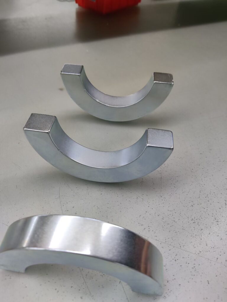
Sharp internal or external corners concentrate stress. Thin walls, narrow bridges, and deep slots are especially sensitive during machining, coating, transport, and assembly. Chamfers, radii, and more uniform cross-sections can materially reduce breakage risk. Our NdFeB arc magnets, for example, are reviewed for edge geometry and handling strategy as well as magnetic performance.
Uneven adhesive bondlines
If adhesive is applied in isolated hard spots, cure shrinkage and thermal expansion can create concentrated loads. A controlled bondline thickness and an adhesive with suitable modulus, temperature capability, and chemical compatibility help distribute stress.
Thermal mismatch
Magnets, steel, aluminum, plastics, and adhesives expand at different rates. Temperature cycling can place the magnet in tension or shear, particularly in a rigid pocket. The full assembly should be reviewed across its minimum and maximum temperatures rather than only at room temperature.
Machining damage
Excessive grinding force, poor support, local overheating, or an aggressive feed can initiate microcracks. Final geometry should be planned around feasible grinding direction, fixture contact, and edge protection. Complex features may be possible, but a slightly different geometry often provides better yield and long-term reliability.
Does the Coating Prevent Breakage?
No. Nickel-copper-nickel, zinc, epoxy, passivation, and other protective systems are primarily selected to reduce corrosion or satisfy surface requirements. A coating can offer limited resistance to light abrasion, but it does not transform brittle NdFeB into a ductile structural material.
Coating peel, corrosion expansion, edge chipping, and a true body crack are different failure modes. A dark line at an edge may be surface damage, while a crack passing through the magnet can affect both mechanical integrity and magnetic-circuit consistency. Inspection should identify the actual failure before the corrective action is chosen.
How to Design a More Reliable NdFeB Magnet Assembly
- Add practical chamfers or radii at vulnerable edges and avoid unnecessarily thin sections.
- Use a housing, carrier, sleeve, or steel back iron to support the magnet mechanically.
- Prefer controlled adhesive bonding over direct interference loading where possible.
- Specify bondline thickness and allow for differential thermal expansion.
- Keep assembly force off the magnet face and avoid using the magnet as a stop.
- Use fixtures, spacers, and nonmagnetic tools to control attraction during assembly.
- When the process permits, assemble before magnetization to reduce collision risk.
- Protect finished parts with individual cavities, separators, and orientation controls in packaging.
For custom shapes and application-specific grades, see our sintered NdFeB magnet capabilities. The best solution normally balances magnetic output, manufacturability, corrosion protection, and mechanical support.
Inspection and Validation
Visual and dimensional inspection can identify chips, edge damage, coating defects, and gross cracks. Magnification may be useful for critical surfaces. Magnetic inspection using flux, surface field, a Helmholtz coil, pull-force testing, or application-level output can confirm consistency, but a magnetic test alone does not prove the absence of a mechanical crack.
For demanding assemblies, validation may also include thermal cycling, vibration, shock, adhesion testing, corrosion exposure, and controlled destructive sampling. Acceptance criteria should define permissible edge chips and cosmetic marks because an undefined expectation can create unnecessary rejection without improving functional reliability.
How Guande Reduces Breakage Risk
Guande supports grade selection, geometry review, magnetization planning, coatings, precision grinding, bonding, magnet-to-metal assembly, and inspection. During design-for-manufacturing review, we examine vulnerable edges, load paths, fixture access, bondline control, magnetic assembly forces, and packaging. For a complete solution, our custom magnetic assemblies can place the brittle magnetic element inside a mechanically robust structure.
Frequently Asked Questions
Can a cracked NdFeB magnet still work?
It may still produce a magnetic field, but the crack can reduce structural security, change the air gap, damage the coating, and create contamination. A cracked part should be evaluated against the actual application rather than reused automatically.
Are bonded NdFeB magnets less brittle?
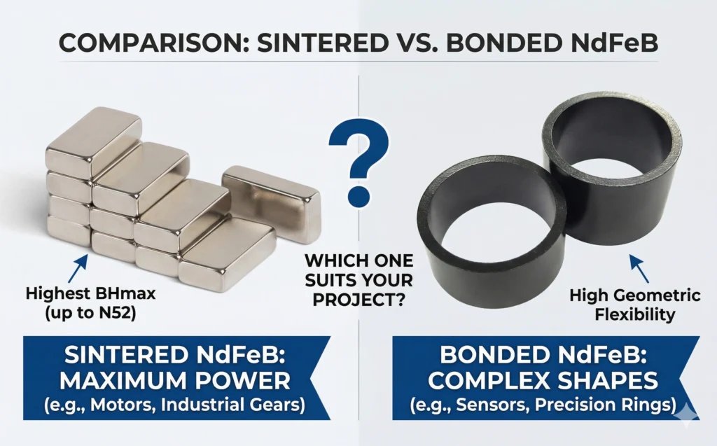
Bonded magnets contain magnetic powder in a polymer matrix and are generally more tolerant of complex shapes and handling, but they have lower magnetic energy than sintered NdFeB. The correct choice depends on force, geometry, environment, and manufacturing volume.
Can a higher NdFeB grade prevent chipping?
Not necessarily. Magnetic grade mainly defines magnetic properties and temperature capability. Mechanical reliability still depends on geometry, process, coating, handling, and assembly design.
Send Guande your drawing, load conditions, temperature range, coating requirement, and assembly method for a practical NdFeB design review.