NdFeB magnets provide the rotor field in many brushless DC motors. Electronic commutation switches current through the stator windings, creating a rotating magnetic field. The permanent-magnet rotor follows that field and produces torque without brushes or a mechanical commutator.
NdFeB is widely used because its high remanence and energy product support compact motors with high torque density. Reliable performance still depends on intrinsic coercivity, rotor temperature, pole geometry, air gap, steel saturation, magnet retention, and control strategy.
BLDC Motor Working Principle
| DC supply | → | Electronic inverter | → | Three-phase stator current |
|---|---|---|---|---|
| Electrical energy | → | Timed semiconductor switching | → | Rotating stator field |
| NdFeB rotor poles | ↔ | Air-gap field interaction | → | Torque and rotation |
Hall sensors, an encoder, or sensorless back-EMF estimation provides rotor position for commutation. Motors designed for trapezoidal back-EMF are commonly called BLDC motors; sinusoidal permanent-magnet synchronous motors use closely related hardware with different winding and control targets.
Where the NdFeB Magnets Are Installed
Surface permanent-magnet inner rotor
Arc segments or blocks are bonded to the outside of a steel rotor core. The structure is simple and provides strong air-gap flux. A sleeve, bandage, or mechanical feature may be required at high speed. The sleeve and adhesive layers add effective air gap.
Interior permanent-magnet rotor
Magnets are inserted into slots inside the rotor laminations. The steel bridges provide mechanical retention and can add reluctance torque. Flux barriers, bridge thickness, and local saturation must be optimized. Interior magnets also face reverse fields during high-current and fault conditions.
Outer rotor
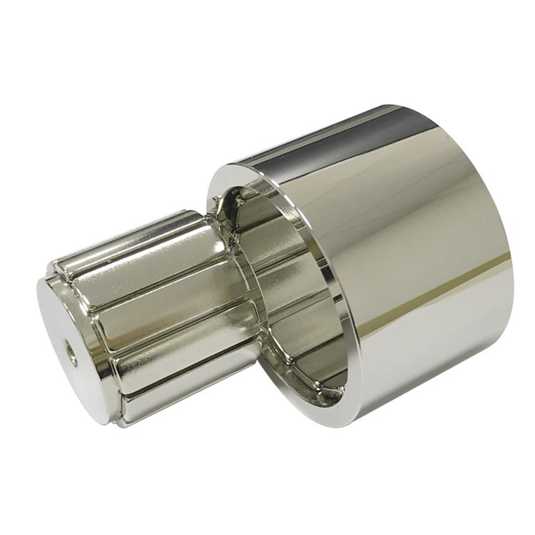
Magnets are bonded to the inside of a rotating steel cup. The larger effective radius supports high torque and smooth low-speed operation, which suits fans, drones, e-bikes, and compact direct-drive systems. Centrifugal force presses the magnets outward into the cup, but adhesive, corrosion protection, and impact loads still require validation.
Bonded multipole ring
A molded NdFeB ring can be magnetized with multiple poles after molding or assembly. It simplifies handling and can reduce pole-to-pole variation, but its magnetic energy is lower than sintered NdFeB. It is useful when thin walls, complex geometry, and production integration are more important than maximum torque density.
| Rotor type | Typical magnet form | Main advantage | Main design risk |
|---|---|---|---|
| SPM inner rotor | Arc segments or blocks | Simple, high air-gap flux | High-speed retention |
| IPM inner rotor | Blocks or shaped segments | Mechanical containment and reluctance torque | Bridge saturation and demagnetization |
| Outer rotor | Arc segments, blocks, or multipole ring | High torque at low speed | Bonding, cup tolerance, corrosion |
| Axial-flux rotor | Trapezoids or sectors | Short axial package | Axial force, flatness, retention |
Why NdFeB Improves Motor Performance
- High Br supports strong air-gap flux and back-EMF in a compact rotor.
- High (BH)max reduces magnet volume for a given magnetic loading.
- Multiple coercivity families allow designs for different temperatures and reverse fields.
- Arc, block, segment, ring, and custom magnetization options support varied motor topologies.
The strongest room-temperature grade is not automatically the best motor grade. A lower-energy H, SH, UH, EH, or AH material may retain more usable flux under high temperature and armature reaction.
Key Magnetic Design Parameters
| Parameter | Representative engineering reference | Design impact |
|---|---|---|
| NdFeB Br | Roughly 1.2-1.5 T by grade | Air-gap flux and back-EMF potential |
| Intrinsic coercivity Hcj | About 950 to above 2,300 kA/m by family | Hot and fault-current demagnetization margin |
| Pole-arc / pole-pitch ratio | Often starts around 0.7-0.95 | Average torque, back-EMF shape, cogging, leakage |
| Mechanical air gap | Application-specific; minimize while protecting runout clearance | Flux density, current demand, acoustic behavior |
| Magnet thickness | Set by load line and required flux | Output, demagnetization resistance, cost |
| Operating temperature | Use magnet temperature, not ambient only | Br reduction and irreversible-loss risk |
These ranges are starting references, not universal specifications. Rotor diameter, speed, slot/pole combination, winding, lamination material, cooling, duty cycle, and control current must be solved together.
Pole Arc, Air Gap, and Torque Ripple
A larger pole arc can increase average air-gap flux, but it can also increase leakage, cogging torque, and harmonic content. Magnet edge shaping, pole-arc optimization, rotor skew, stator-slot design, and current control are used to balance torque density against vibration and noise.
The air gap includes more than nominal mechanical clearance. Magnet coating, adhesive, retaining sleeve, rotor runout, stator eccentricity, and thermal expansion all contribute. A small design gap improves flux but reduces manufacturing and bearing tolerance margin.
Magnetization Direction and Pole Sequence
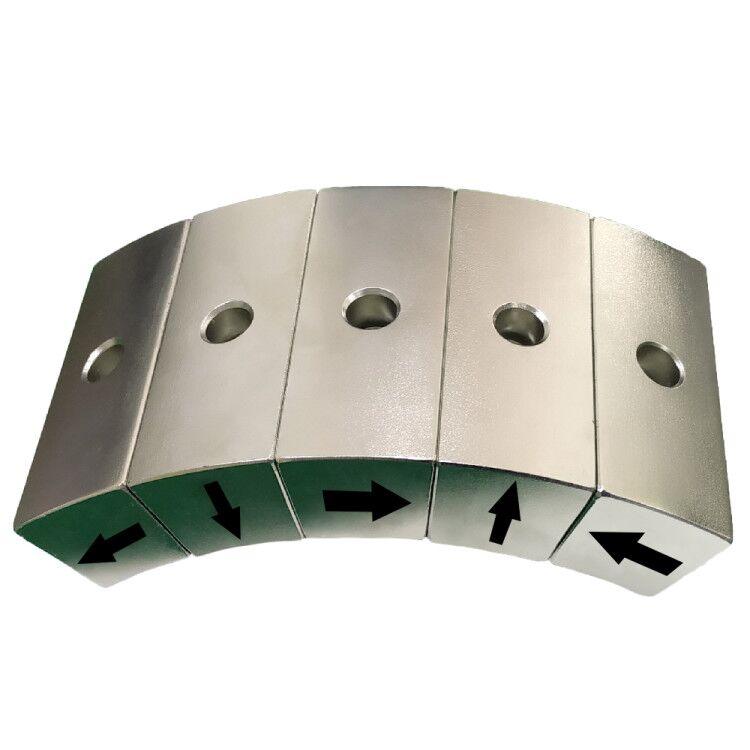
Arc magnets can use radial, parallel, or engineered magnetization. Radial magnetization follows the rotor radius and can support a consistent air-gap field, while parallel magnetization is often easier to manufacture for small arcs. A multipole ring is magnetized with alternating poles around the circumference.
Each magnet must be installed with the correct N/S sequence. One reversed segment can create local torque loss, vibration, and abnormal back-EMF. Guande verifies orientation before assembly and can map the completed rotor after bonding.
Temperature and Demagnetization
Motor magnets are heated by stator copper loss, rotor eddy-current loss, bearings, ambient conditions, and limited cooling. During acceleration or a fault, stator current creates a reverse magnetic field. The worst case is therefore the combined hot temperature and reverse field, not the no-load room-temperature state.
Finite-element analysis should check the minimum operating point throughout the magnet, especially at edges and near rotor bridges. Prototype validation can compare magnetic moment or back-EMF before and after hot current loading. Irreversible change must remain within the agreed limit.
Mechanical Retention and Corrosion Protection
Sintered NdFeB is hard and brittle. It should not carry rotor impact or assembly press loads. Adhesive joints need controlled bondline thickness, surface preparation, cure verification, and temperature compatibility. High-speed SPM rotors may use carbon-fiber, stainless, or nonmagnetic-alloy sleeves, with sleeve loss and added gap included in the design.
Ni-Cu-Ni, epoxy, zinc, passivation, or sealed rotor construction may be selected according to humidity, coolant, salt, and cleanliness. Coating alone does not replace edge protection or environmental sealing.
Where NdFeB BLDC Motors Are Used
- Cooling fans, blowers, pumps, and HVAC compressors.
- Drones, model aircraft, and electric propulsion.
- Robot joints, servo axes, gimbals, and automated equipment.
- Power tools, vacuum cleaners, and household appliances.
- E-bikes, scooters, electric power steering, and vehicle auxiliaries.
- Spindles, medical devices, and compact precision actuators.
Guande Motor-Magnet Capability
Guande supplies NdFeB arc magnets, blocks, segments, and custom magnetization for inner-rotor, outer-rotor, axial-flux, and IPM designs. Our rotor magnet assemblies can include steel cores or cups, bonding, orientation fixtures, sleeves, dimensional inspection, magnetic mapping, runout, and balance control.
For new projects, we review the hot operating point, pole pattern, adhesive and retention method, coating, tolerances, and measurable production acceptance criteria. This keeps material selection connected to motor output instead of treating the magnet as an isolated catalog part.
Frequently Asked Questions
Are all BLDC motor magnets radially magnetized?
No. Radial, parallel, multipole, axial, and Halbach-style patterns are used according to rotor geometry and performance targets.
Can N52 replace an N42SH motor magnet?
Not without analysis. N52 may provide higher room-temperature Br but lower hot coercivity. It can suffer irreversible loss under motor temperature and reverse current.
How should a finished rotor be tested?
Useful tests include pole sequence, surface-field mapping, magnetic moment, back-EMF, dimensions, runout, balance, adhesion or overspeed, temperature rise, and hot demagnetization validation.
Send Guande the rotor drawing, speed, pole count, air gap, current, temperature, and back-EMF or torque target for a practical BLDC magnet review.