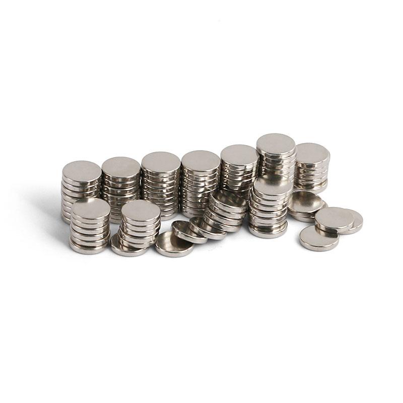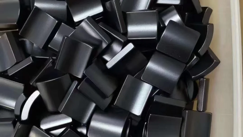
A sintered NdFeB magnet contains a reactive rare-earth-rich phase at its grain boundaries. When moisture, salt or acidic residue reaches an unprotected surface, localized corrosion can expand beneath the surface and reduce mechanical integrity. The neodymium magnet plating process therefore has two jobs: isolate the magnet from its environment and provide a surface compatible with bonding, assembly and handling.
Engineering point: coating choice cannot be separated from edge geometry, operating temperature, adhesive, humidity and expected handling. A thicker coating does not automatically compensate for poor surface preparation or sharp corners.
Why NdFeB Requires Surface Protection
After sintering, heat treatment and precision grinding, the magnet surface contains grinding debris, oxides and contaminants. Bare material may look stable in a dry room but deteriorate rapidly when exposed to condensation or chloride. Plating creates a controlled barrier, improves appearance and can raise bond consistency. It does not change the magnet grade or its intrinsic coercivity.
Typical Plating Process
| Stage | Purpose | Key control |
|---|---|---|
| 1. Incoming inspection | Confirm dimensions, chips and surface condition | Reject cracks that coating could hide |
| 2. Degreasing | Remove oil and organic residue | Clean chemistry and controlled time |
| 3. Activation | Remove weak oxide and activate the surface | Avoid excessive attack on Nd-rich grain boundaries |
| 4. Strike or base layer | Create adhesion and seal the substrate | Coverage at corners and recesses |
| 5. Functional layers | Build corrosion resistance and finish | Current density, bath chemistry and thickness |
| 6. Rinsing and drying | Remove process residue | Clean water, rapid complete drying |
| 7. Final inspection | Verify appearance, thickness and adhesion | Sampling plan matched to application risk |
NdFeB is brittle, so barrel loading, contact pressure and part-to-part collision must be controlled. Small discs may suit barrel processing, while large rings, thin segments and parts with critical cosmetic faces often need racks or dedicated fixtures. Threaded holes and tight recesses also change current distribution and drainage.
Common Coating Systems
| Coating | Typical total thickness | Strengths | Design limits |
|---|---|---|---|
| Ni-Cu-Ni | About 10–25 µm | Durable metallic finish; good wear and assembly handling | Conductive; cut edges and severe salt exposure need review |
| Zn | About 5–15 µm | Cost-effective; useful sacrificial behavior | Softer finish and appearance variation |
| Epoxy | About 15–30 µm | Good barrier coverage and electrical isolation options | Can chip under impact; temperature and adhesive compatibility matter |
| Ni-Cu-Ni + epoxy | About 20–40 µm | Metal base plus polymer barrier for demanding humidity | More dimensional build and process cost |
| Phosphate or passivation | Thin conversion layer | Low dimensional change; useful as a bonding pretreatment | Not a substitute for a robust barrier in wet service |
| Parylene | Application-specific | Conformal, pinhole-resistant coverage for complex geometry | Higher cost and careful masking requirements |
These are practical ranges, not universal specifications. Final thickness must be stated on the drawing because it affects finished dimensions, air gaps and press fits. For example, a 20 µm total build can be significant on a small precision rotor magnet.
Preparation and Edge Design Matter
Sharp edges concentrate stress and electric current, making coating thickness less uniform and increasing the risk of chipping. A small chamfer or radius normally improves both handling and coverage. The allowable radius must still respect magnetic working area and assembly clearance. Blind holes, counterbores and deep slots should be reviewed for trapped solution and incomplete drying.
Coating is applied after most dimensional grinding. Masking may be specified for bonding faces, electrical contact areas or datum surfaces, but every mask line is also a possible transition point for moisture. When an adhesive joint is critical, we recommend confirming surface energy and lap-shear performance with the exact adhesive rather than relying only on a generic coating description.
How Coating Quality Is Verified
A useful inspection plan combines dimensional and functional checks. X-ray fluorescence can measure metallic layer thickness without cutting the part. Cross-section microscopy reveals individual Ni, Cu and Ni layers when process validation is required. Adhesion can be evaluated by an agreed tape, thermal-shock or mechanical method. Salt-spray and pressure-cooker tests are comparative accelerated tests; they do not directly predict service life unless correlated with the actual environment.
Visual inspection should define acceptable pores, blisters, exposed corners, stains and rack marks. Sampling level depends on the consequence of failure. Magnets for an enclosed office sensor do not need the same validation as magnets installed in a wet motor or outdoor actuator.
Coating Compatibility with Magnetization and Assembly
Magnets may be plated before or after magnetization, depending on shape, fixture capability and handling risk. Processing unmagnetized parts reduces attraction to tanks, racks and neighboring parts, but the later magnetizing pulse must not damage the finish. If parts are magnetized first, plating equipment must control magnetic attraction and accumulated debris. The agreed sequence should be frozen during qualification.
Assembly cleaning also matters. Strong alkaline cleaners, abrasive blasting or uncontrolled ultrasonic cycles can damage a finished layer. Press fits can crack both the brittle substrate and the coating, while an adhesive with excessive shrinkage can load sharp edges. For custom neodymium magnets, coating qualification should therefore include the actual assembly method, not only a coupon test.
Specifying a Coated Magnet
A complete request should state finished dimensions and tolerances, coating type and thickness, masked areas, operating temperature, exposure to salt or chemicals, adhesive and cleaning method, cosmetic requirements and the applicable test standard. The selected neodymium magnet grades must also tolerate the process temperature and later operating load line.
Guande supports grinding, chamfer control, Ni-Cu-Ni, zinc, epoxy and application-specific surface systems for sintered NdFeB magnets. Our arc magnets and block magnets can be supplied to finished coated dimensions. When the magnet is bonded into steel or a rotor, our custom magnetic assembly service evaluates coating, adhesive and retention together.
Send the drawing and environmental requirements through our engineering quote form. We will recommend a practical neodymium magnet coating and inspection plan instead of specifying protection by appearance alone.