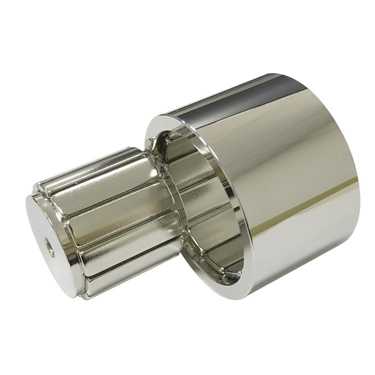
A permanent magnet synchronous motor (PMSM) uses permanent magnets on or inside the rotor to establish rotor flux. The stator produces a rotating magnetic field, and the rotor follows that field at synchronous speed. Because the rotor does not need induction current to create its main field, the design can reduce rotor losses and deliver high torque from a compact package.
Practical rule: a PMSM is not automatically the best motor. Its advantage depends on the duty cycle, speed range, inverter strategy, cooling, magnet temperature and total system cost.
Why PMSMs Are Efficient
In an induction motor, slip is required to induce rotor current, and that current produces rotor copper loss. A PMSM has no slip in steady synchronous operation and no rotor excitation winding. This reduces one important loss source, especially at partial load. It also lowers rotor heating, although stator copper loss, iron loss, mechanical loss and inverter loss remain.
Higher efficiency is most valuable in long-duty industrial drives, compressors, pumps, electric vehicles and battery-powered equipment. Less loss can reduce cooling demand or allow more output within the same thermal envelope. The actual gain should be measured over the operating map, not at one rated point.
Main Advantages and Their Engineering Meaning
| Advantage | Engineering effect | Condition for realizing it |
|---|---|---|
| High efficiency | Lower rotor excitation loss and reduced heat | Correct electromagnetic and inverter design |
| High torque density | Smaller motor for a given torque | Strong air-gap flux and adequate cooling |
| Fast dynamic response | Precise torque control and acceleration | Encoder or robust sensorless control |
| High power factor | Lower current for a given output | Operating point and field-weakening strategy |
| Low rotor loss | Lower rotor temperature than an induction cage in many duties | Eddy-current segmentation where speed is high |
| Good low-speed torque | Useful for direct drive and servo control | Inverter-controlled current and suitable pole design |
Surface and Interior Permanent Magnet Rotors
| Rotor type | Magnet arrangement | Strengths | Design concerns |
|---|---|---|---|
| SPM | Magnets bonded or retained near the rotor surface | Simple magnetic circuit; low saliency; smooth servo behavior | Mechanical retention and field weakening |
| IPM | Magnets embedded in rotor slots | Magnet torque plus reluctance torque; broad speed range | Complex laminations, leakage and bridge stress |
| Inset | Magnets recessed partly below the surface | Compromise between retention and air-gap coupling | Manufacturing tolerance and leakage flux |
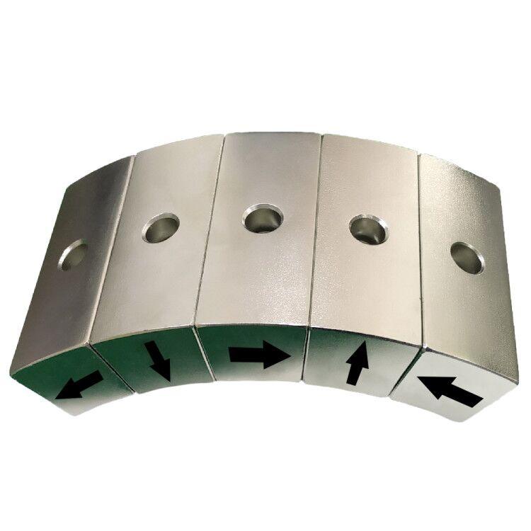
| Halbach rotor | Magnetization rotates around the circumference | Concentrated working-side flux and potentially low back iron | Segment orientation and assembly force |
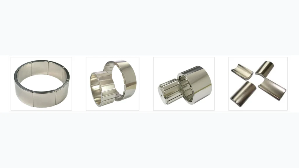
SPM rotors often use arc segments with radial or parallel magnetization. IPM designs may use rectangular or V-shaped magnets. A neodymium magnet for motor service must therefore control geometry, magnetization direction and pole consistency, not only Br.
Magnet Grade and Thermal Margin
The highest room-temperature energy product is rarely the only target. Rotor magnets experience continuous temperature, short overloads and an opposing armature-reaction field. High-coercivity H, SH, UH or EH neodymium magnet grades may give a safer hot operating point than a higher-remanence standard grade. The decision should use the B-H curve at maximum magnet temperature and the motor’s worst negative d-axis current.
Magnets are electrically conductive. At high electrical frequency, slot harmonics and inverter harmonics can create magnet eddy-current loss. Axial or circumferential segmentation interrupts current paths, while adhesive gaps and coatings affect heat transfer. The segmentation pattern must be included in electromagnetic and mechanical validation.
What PMSMs Require in Return
PMSMs normally need an electronic inverter and position-aware control. Field-oriented control provides accurate torque but adds software and sensor requirements. At high speed, field weakening applies opposing current, which increases demagnetization risk. Rare-earth price exposure, magnet retention and safe assembly handling must also be considered.
For high-speed rotors, centrifugal stress acts on every segment and bond line. Surface magnets may need a nonmagnetic sleeve or mechanical banding. Adhesive selection must consider shear strength at temperature, thermal expansion, curing conditions and chemical exposure. Rotor balance after assembly is part of the system specification.
Typical PMSM Applications
PMSMs are common in electric traction, industrial servo axes, collaborative robots, HVAC compressors, pumps, machine-tool spindles, drones and direct-drive systems. The preferred topology changes with speed, torque ripple, acoustic noise, envelope and cost. A compact servo may prioritize low cogging, while traction needs a wide constant-power speed range and strong irreversible-demagnetization margin.
Parameters to Freeze Before Magnet Sourcing
Motor teams should freeze the magnet envelope, pole count, magnetization direction, minimum Br and Hcj at the specified temperature, coating, segmentation and dimensional datums. A room-temperature pull-force value is not an adequate rotor specification. The supplier also needs the peak rotor temperature, maximum negative d-axis current and expected dwell time at overload.
For assembled rotors, define adhesive bond-line thickness, cure cycle, sleeve material, permitted runout, balance grade and magnetic acceptance limits. Pole-to-pole flux variation and magnetization-angle error often influence torque ripple more directly than a small difference in nominal grade. Prototype back-EMF, no-load loss and thermal tests should close the loop between simulation and production. Guande can provide custom neodymium magnets and matched assembly records for this validation.
Guande supplies precision arc magnets, motor blocks and assembled permanent magnet rotors. Our work covers magnetic-circuit review, segmentation, magnetization, coating, adhesive process, fixture-assisted assembly and magnetic inspection for a neodymium magnet motor. Related options are described on our sintered NdFeB page and custom assembly page.
For a design review, send the lamination drawing, air gap, pole count, speed, current envelope and thermal limits through our quote form. We will evaluate the magnet and rotor assembly against the actual operating map and production tolerances.