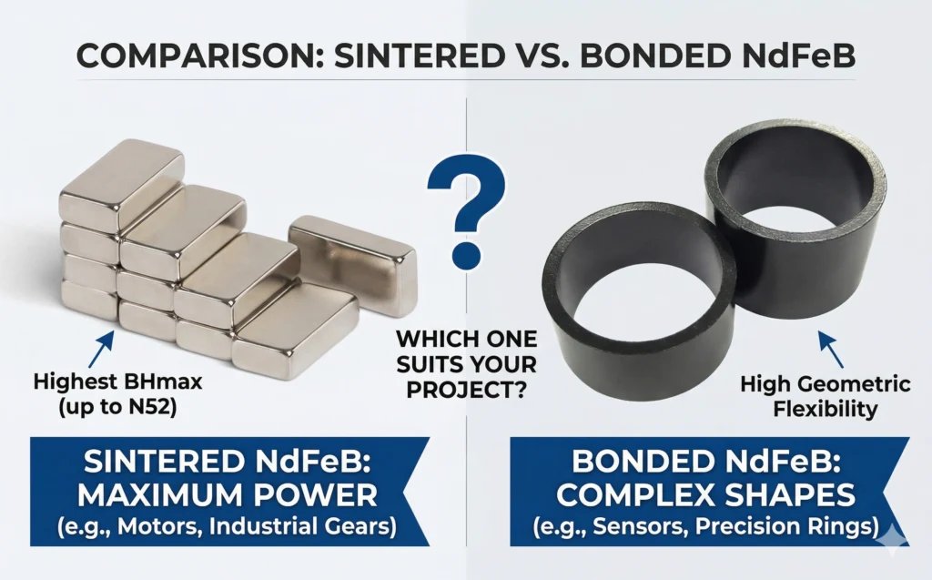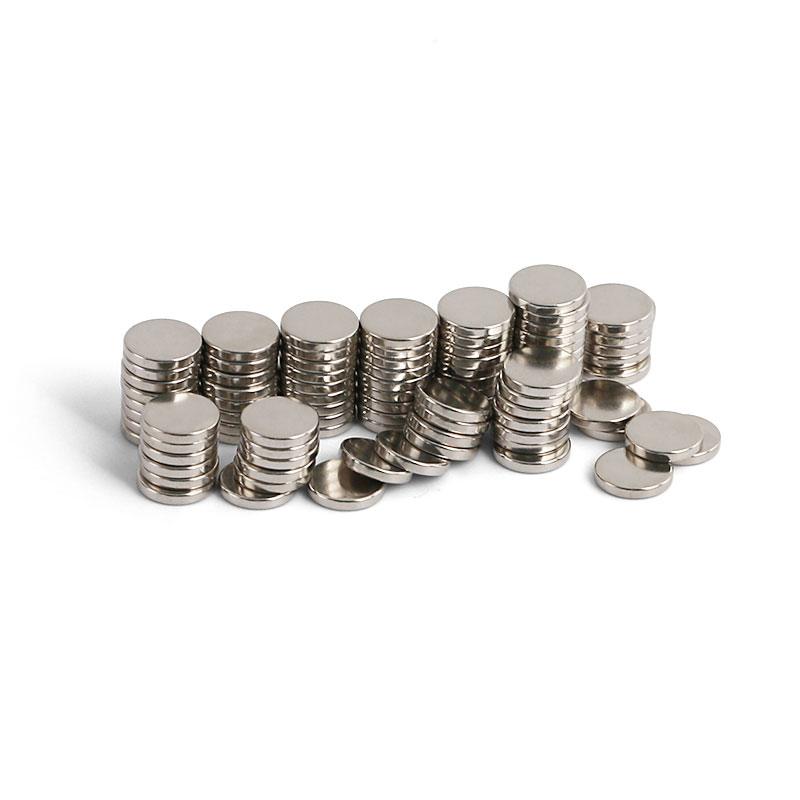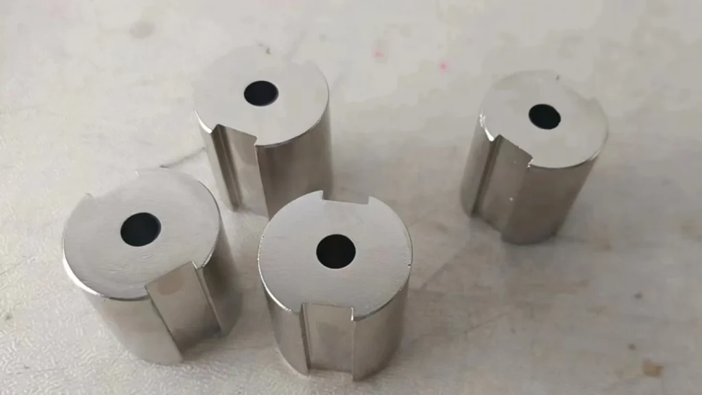
Custom-shaped NdFeB magnets are used when a standard block, disc, ring or arc cannot provide the required magnetic field, assembly clearance or mechanical interface. Typical features include slots, steps, flats, keyways, grooves, asymmetric outside profiles, off-center holes and compound radii. These parts can solve a real packaging problem, but their geometry must be designed around a brittle sintered material rather than treated like ordinary steel.
Engineering rule: define the magnetic circuit, magnetization direction, coating and inspection method before finalizing the shape. A feature that is easy to draw may be expensive to grind, difficult to coat or impossible to magnetize uniformly.
Why Sintered NdFeB Requires a Different Machining Strategy
Sintered NdFeB is hard, brittle and sensitive to tensile stress. It does not form a continuous chip like mild steel. Conventional turning or milling can create edge chipping, microcracks and local heating. Production therefore relies mainly on abrasive cutting, precision grinding and controlled electrical-discharge processes, followed by cleaning and surface protection.
Machining is normally completed before final coating and magnetization. Working with an unmagnetized blank reduces handling force and prevents abrasive swarf from collecting on the part. After finishing, the magnet is cleaned, plated or coated, magnetized in a dedicated fixture and inspected.
Common Processing Methods
| Method | Suitable features | Main control point |
|---|---|---|
| Diamond slicing | Thin sections, segments and straight cuts | Kerf loss, parallelism and edge support |
| Surface grinding | Thickness, flats, steps and reference faces | Coolant, wheel condition and flatness |
| ID/OD grinding | Holes, cylindrical surfaces and concentric profiles | Wall thickness, runout and chipping |
| Profile grinding | Slots, notches, radii and repeated contours | Tool access and corner stress |
| Wire EDM | Complex through-profiles and narrow internal features | Recast layer, heat effect and subsequent cleaning |
| Chamfering/tumbling | Edge relief before coating | Uniformity and dimensional allowance |
Wire EDM can reduce tooling complexity for some profiles, but it is not automatically the lowest-cost process. Part thickness, cut length, surface condition, electrode wire, machine time and post-process requirements all matter. High-volume parts often justify a near-net pressed blank plus limited finish grinding.
Practical Geometry and Tolerance Guidance
| Design item | Practical starting point | Why it matters |
|---|---|---|
| Sharp internal corners | Add the largest functional radius | Reduces crack initiation and grinding difficulty |
| Thin bridges or walls | Avoid unless magnetically essential | Fragile during machining, coating and assembly |
| Edge condition | Specify a chamfer or radius | Protects the coating and reduces chipping |
| Ground dimensions | ±0.05 mm is a common review baseline | Tighter values require feature-specific agreement |
| Hole-to-OD relation | Define concentricity and datum faces | Prevents an incomplete tolerance scheme |
| Coating allowance | State whether dimensions are before or after plating | Coating thickness changes finished size |
These values are not universal production guarantees. Size, grade, aspect ratio, process route and inspection access determine achievable tolerance. A narrow slot may need a different control plan from the outside diameter of the same part.
Cost, Yield and Prototype Strategy
Custom geometry affects cost through blank utilization, grinding time, fixture quantity, tool wear, coating yield and inspection time. Removing a large volume from a standard block is usually less efficient than starting with a closer pressed blank. Conversely, a dedicated near-net tool may not be economical for a small prototype run.
A practical development route starts with a limited uncoated sample to prove machining, dimensions and assembly fit. Coated and magnetized samples then confirm the final air-gap field and functional output. Before scale-up, the supplier should review breakage, coating defects, magnetization yield and gauge repeatability. This sequence separates geometry problems from magnetic-circuit problems and avoids committing to production tooling too early.
Magnetization Direction Must Match the Shape
A custom profile is useful only when the magnetic orientation supports the working air gap. Axial, diametrical, radial and multipole patterns require different fixtures and can produce different local field distributions. An asymmetric notch may serve as an assembly key, but it can also change the local permeance coefficient and create a demagnetization-sensitive region.
The magnetizing fixture must deliver enough field throughout the full cross-section. Very thick sections, high-coercivity grades and unusual pole patterns require early fixture review. Where the finished part cannot be magnetized reliably, the design may be divided into simpler pieces and assembled after magnetization.
Coating and Assembly Considerations
NdFeB is vulnerable to corrosion because its microstructure contains rare-earth-rich boundary phases. Ni-Cu-Ni, zinc, epoxy and application-specific systems are selected according to humidity, salt, chemicals, adhesive and temperature. Deep slots and sharp recesses are harder to coat uniformly, so drainage, racking and edge geometry must be considered.
The magnet should not carry structural load. Retaining features, steel carriers, adhesives and mechanical stops should support impact and vibration. For an integrated part, Guande’s custom magnetic assembly process can connect the magnet geometry to the steel circuit, bonding fixture and inspection plan.
Where Custom Shapes Are Used
| Application | Typical shape feature | Design objective |
|---|---|---|
| Motor rotors | Arc, skew, step or retaining notch | Control air-gap flux and mechanical retention |
| Position sensors | D-flat, slot or eccentric profile | Create a repeatable field signature |
| Magnetic couplings | Segment, wedge or curved pole | Fit a circular torque-transmission path |
| Medical and analytical devices | Compact asymmetric profile | Place flux around restricted components |
| Fixtures and latches | Counterbore, keyway or mounting flat | Integrate location and one-sided attraction |
| Linear motors | Trapezoid, skewed block or matched array | Manage force ripple and installation envelope |
From Drawing to Repeatable Production
Guande reviews material grade, blank strategy, grinding datums, fragile sections, coating allowance, magnetization direction and measurement access before quotation. We support sintered NdFeB magnets, including arc magnets, block magnets and application-specific profiles.
Inspection can include CMM dimensions, optical profile checks, coating thickness, adhesion, magnetic moment, surface flux and fixture-based functional testing. For stable mass production, the drawing should identify critical-to-function dimensions rather than applying the tightest tolerance everywhere.
Send the 2D/3D drawing, magnetization direction, working temperature, coating environment and annual quantity. We will propose a practical manufacturing and validation route for the required shape.