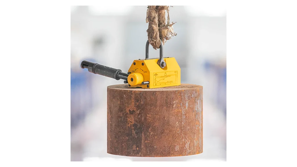
Large magnetic lifter design is a combined magnetic, mechanical and safety-engineering task. The magnet circuit must create enough usable force through the real steel surface, while the housing, lifting eye, beam and switching mechanism transfer the load without relying on brittle magnets as structural members.
Safety boundary: a magnet assembly is lifting equipment only after the complete system has been designed, proof-tested, rated and certified for the intended load and jurisdiction. Never determine a safe working load from a magnet pull-force calculation alone.
How the Magnetic Circuit Produces Lift
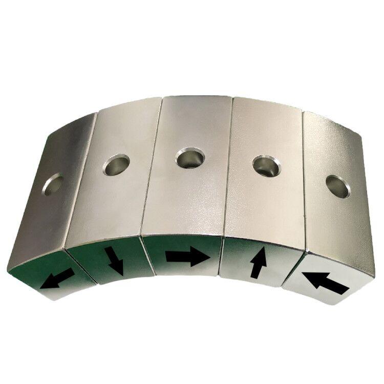
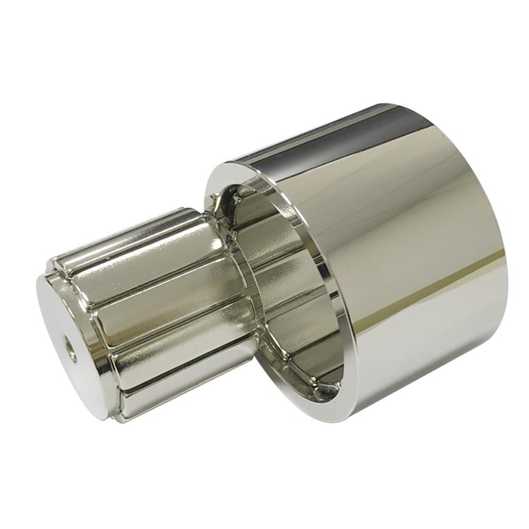
Permanent-magnet lifters use NdFeB or another permanent magnet source, low-carbon-steel yokes and shaped pole shoes. In the ON state, flux leaves one pole, crosses the contact interface, travels through the steel load and returns through the opposite pole. In OFF, a rotor or steel shunt redirects most flux inside the housing.
An idealized magnetic pressure estimate is:
F ≈ B²A / (2μ0)
Here, B is interface flux density and A is effective pole area. Real force is lower because of leakage, steel saturation, surface gaps, finite plate thickness, pole-edge effects and uneven contact.
Why Large Lifters Use Multiple Poles or Modules
Simply scaling one small lifter produces uneven contact and excessive structural weight. Large systems often distribute several magnetic modules across a beam. This increases active area and allows the system to follow plate flatness, but each module must share the load predictably.
| Design element | Function | Critical control |
|---|---|---|
| Magnetic modules | Create multiple controlled flux loops | Matched output and pole orientation |
| Equalizing beam | Transfers crane load across modules | Deflection, fatigue and center of gravity |
| Compliant suspension | Accommodates small flatness differences | Travel limit and load distribution |
| Pole shoes | Match plate, block or round-stock geometry | Wear, saturation and contact area |
| Switch and lock | Controls ON/OFF state | Positive position and accidental-release prevention |
| Sensors/indicators | Confirm state or contact conditions | Functional-safety architecture and diagnostics |
Load Conditions That Reduce Lifting Capacity
| Condition | Why force decreases | Required response |
|---|---|---|
| Paint, rust, scale or oil | Creates an effective air gap | Test the maximum actual surface condition |
| Thin plate | Steel saturates and cannot carry all return flux | Use a plate-thickness derating curve |
| Round or curved load | Contact area becomes narrow | Use matched V-poles and a dedicated rating |
| High-carbon or alloy steel | Permeability differs from reference steel | Validate the real grade and heat treatment |
| Off-center pickup | Creates peel and tipping moment | Align above the measured center of gravity |
| Shock or rapid travel | Dynamic load exceeds static weight | Control crane acceleration and apply required safety factors |
| High temperature | Reduces magnet output and coercivity | Rate the complete system at temperature |
Permanent, Electro-Permanent or Electromagnetic?
| System | Hold power | Best fit | Main limitation |
|---|---|---|---|
| Manual permanent | No continuous power | Blocks, dies and smaller plate handling | Manual switching and limited automation feedback |
| Electro-permanent | Short pulse to switch; no continuous hold power | Automated large-plate and robotic systems | Control, coil and state-validation complexity |
| Electromagnetic | Continuous electrical power | Fast cycling and adjustable field | Heat and safe response to power loss |
Verification Before a Working Load Is Assigned
- Define material, minimum thickness, maximum gap, geometry and temperature.
- Calculate the magnetic circuit and structural load path separately.
- Measure module force and the assembled beam’s load distribution.
- Proof-test using the applicable standard and certified equipment.
- Verify switching, locking, indicators, residual force and failure response.
- Document inspection intervals, wear limits and operator procedures.
A low-height trial lift and exclusion zone remain necessary in operation. People must never stand beneath a suspended load.
Guande Magnetic Assembly Capability
Guande can support magnet grade, orientation, pole geometry, yoke saturation, air-gap analysis, assembly fixtures and force-versus-gap testing for custom magnetic assemblies. Related components include custom block magnets and high-coercivity sintered NdFeB magnets.
Our earlier article explains the ON/OFF principle of switchable lifting magnets. Send the load material, dimensions, mass, surface, handling direction and duty cycle for an engineering review. Final equipment certification remains with the qualified lifting-system manufacturer.