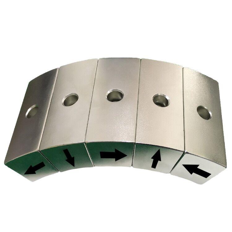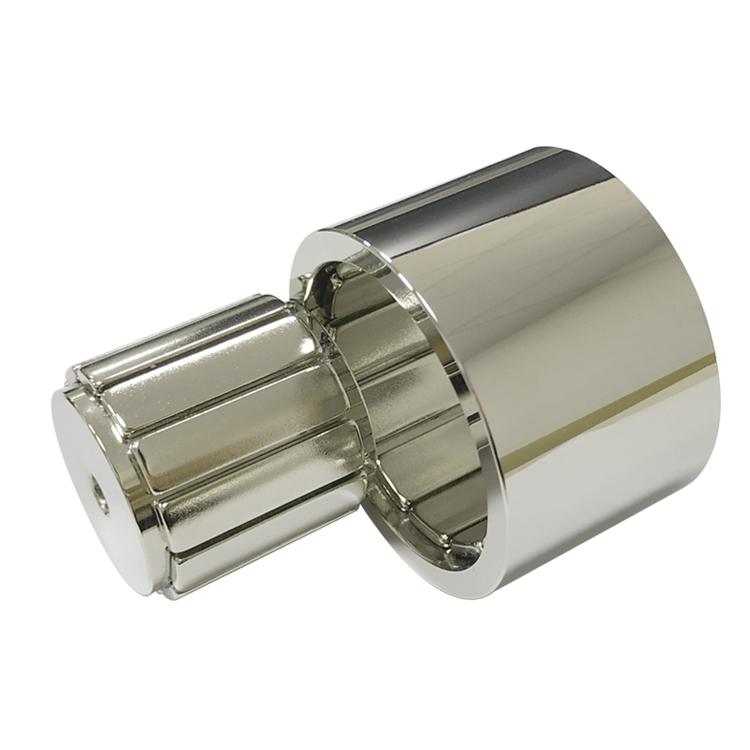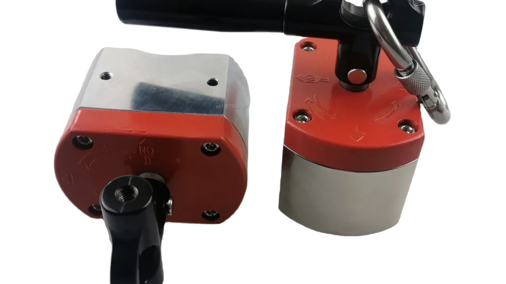
A switchable lifting magnet holds ferromagnetic loads without continuous electrical power. Moving the handle does not demagnetize the permanent magnet. It rotates or shifts an internal magnetic element so the flux follows either an external path through the workpiece in the ON state or an internal low-reluctance path in the OFF state.
Safety boundary: a magnetic holder becomes lifting equipment only when the complete product—magnetic circuit, housing, shaft, handle, lock, lifting eye and labeling—has been designed, tested and certified for the intended load and jurisdiction.
The ON/OFF Magnetic-Circuit Principle
Permanent magnets supply magnetomotive force continuously. Low-carbon-steel pole pieces guide that flux. In ON, the internal rotor aligns so flux leaves one pole shoe, crosses the contact interface into the load and returns through the opposite pole. The steel load closes the external circuit and creates lifting force.
In OFF, the rotor directs most flux through internal steel bridges rather than the load. Residual attraction remains because of leakage, steel hysteresis and assembly tolerances. “OFF” therefore means a specified low residual force, not zero magnetism.
Main Structure
| Component | Function | Critical control |
|---|---|---|
| Permanent-magnet rotor | Creates and switches the magnetic source | Grade, magnetization, hot coercivity and balance |
| Steel yoke and pole shoes | Carry flux to the workpiece | Cross-section, saturation, flatness and wear |
| Nonmagnetic separators | Keep north and south paths distinct | Thickness, location and mechanical strength |
| Handle, shaft and stops | Rotate the internal circuit | Switch torque, positive end position and fatigue |
| Safety lock | Prevents accidental return to OFF | Positive engagement under vibration and load |
| Lifting eye and body | Transfer the mechanical load | Independent structural path and proof testing |
Why Rated Force Changes in Real Use
Catalog pull is normally measured on a clean, flat, sufficiently thick low-carbon-steel plate with the force perpendicular to the pole face. Paint, rust, mill scale, oil, paper labels and surface roughness create an effective air gap. Curved stock reduces contact area, and thin sheet may saturate before the magnet circuit reaches its potential.
| Load condition | Effect | Required response |
|---|---|---|
| Thin plate | Return path saturates and flexes | Apply a thickness derating curve |
| Paint, scale or rust | Air gap sharply reduces flux | Test at maximum actual gap |
| Round bar or pipe | Small contact area and different flux path | Use V-shaped poles and a cylindrical-load rating |
| High-carbon or alloy steel | Permeability differs from reference steel | Test the actual grade and heat treatment |
| Off-center lift | Creates peel and tipping moment | Position above the center of gravity |
| Shock or rapid crane motion | Dynamic force exceeds static weight | Control acceleration and apply required safety factors |
| Hot workpiece | Magnet output and coercivity decrease | Confirm the complete lifter temperature limit |
Common Switchable Magnet Architectures
- Rotating permanent-magnet rotor: a handle turns the internal magnet between external and internal flux paths.
- Dual-magnet circuit: one magnet rotates so the two sources reinforce in ON and oppose or bypass externally in OFF.
- Moving steel shunt: a low-reluctance bridge redirects flux away from the workpiece.
- Electro-permanent system: a short current pulse changes one magnetic element while permanent magnets hold without continuous power.
Manual lifters are simple and do not need a power cable. Electro-permanent systems can support automation and state feedback, but they add controls, coils, sensors and functional-safety requirements.
The architecture should be selected only after defining the load envelope, duty cycle, release requirement, available actuation method and required feedback.
Application Scenarios
| Application | Why a switchable magnet is useful | Key limitation |
|---|---|---|
| Steel-plate loading | Fast attachment without clamps or power during hold | Plate thickness, flatness and center of gravity |
| Machine-shop handling | Moves blocks, dies and flame-cut parts | Scale, chips, oil and irregular surfaces |
| Welding and fabrication | Temporary positioning of ferrous workpieces | Heat, weld spatter and side loads |
| CNC fixtures | Quick location with clear access to the part | Cutting force, vibration and swarf accumulation |
| Robot end effectors | Low hold-power demand and fast pickup | Part-present sensing and secondary retention |
| Sheet-metal transfer | Clean interface without vacuum leakage | Double-sheet pickup and thin-stock derating |
| Pipe and round-stock handling | Purpose-shaped poles can grip cylindrical targets | Requires a dedicated rating and geometry |
Magnet and Steel Selection
NdFeB is common because it produces strong flux in a compact rotor. SmCo can be evaluated when elevated temperature or corrosion stability dominates. The highest-energy NdFeB grade is not automatically best: if the yoke or workpiece saturates, more magnet volume adds leakage rather than useful lifting force.
Pole width, pole spacing, yoke thickness, rotor clearance and contact geometry must be optimized together. Mechanical components carry the structural load; the brittle magnets should be bonded, supported and protected rather than used as structural members.
Inspection and Safe Operating Sequence
- Verify the load material, thickness, mass, surface and center of gravity.
- Clean and inspect the pole faces, lifting eye, handle and lock.
- Place the unit so the load does not peel or tip away from one edge.
- Move fully to ON and confirm positive lock engagement.
- Perform a low-height trial lift before transport.
- Keep people outside the fall zone and never exceed the rated working load.
- After release, verify OFF residual force and remove accumulated chips.
Production inspection should include dimensions, switch torque, ON pull force, OFF residual force, handle-lock function and proof testing according to the applicable product standard. A result from one steel thickness cannot be transferred to every application.
Guande Switchable Assembly Support
Guande can review magnet grade and orientation, rotor geometry, pole saturation, steel material, clearances, coatings, assembly fixtures and test methods. Related components include custom block magnets, disc magnets and custom magnetic assemblies.
Our scope can include magnetic FEA, controlled insertion, polarity checks, force-versus-gap testing, switch-cycle tests and lot traceability. Final lifting-equipment certification remains the responsibility of the qualified system manufacturer.
Send the load material, thickness, surface, working load, direction, temperature and required safety factor for a practical ON/OFF magnetic-circuit review.