A permanent magnetic coupling can transfer rotary motion between an electronic lock’s motor and latch without a direct shaft passing through the enclosure. A driving rotor and driven rotor carry matched magnetic pole patterns. Their fields interact across a small nonmagnetic barrier, so the inner rotor follows the outer rotor until the required torque exceeds the coupling’s slip torque.
Important distinction: a mechanical permanent-magnet coupling is not the same as an electromagnetic door lock, RFID reader or inductive power link. It transfers mechanical torque; inductive coupling transfers electrical energy or data.
Where the Coupling Fits in an Electronic Lock
In a sealed cabinet, outdoor access unit, medical enclosure or clean-room lock, the motor and electronics may be placed on one side of a moisture barrier while the latch cam sits on the other. A magnetic coupling eliminates the rotating shaft seal. This can reduce water ingress, contamination paths, wear and assembly complexity.
Another architecture uses the coupling as a magnetic clutch. After electronic authorization, a solenoid or miniature motor brings the magnetic rotor pair into alignment or moves a pole piece, allowing the user’s knob to drive the latch. Without authorization, the knob can rotate freely or the coupling slips without transmitting enough torque to release the bolt.
Magnetic Coupling Working Principle
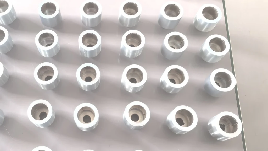
Most compact lock couplings use face-to-face axial rotors or concentric radial rotors. Alternating north and south poles create a restoring torque when the rotors become angularly misaligned. At normal latch load, the driven rotor follows synchronously. At the maximum stable offset, the transmitted magnetic coupling torque reaches a peak. Beyond that point, the rotors slip by one pole pitch.
Slip can protect small gears and motors during a jam or forced rotation, but it must be intentional. A coupling sized too close to normal operating torque may slip during cold-weather seal friction. A coupling sized too high may transmit an attack load into the gearbox or latch.
| Architecture | What the coupling does | Benefit | Main risk |
|---|---|---|---|
| Sealed rotary feedthrough | Transfers motor torque through a nonmagnetic wall | No dynamic shaft seal | Torque falls rapidly with gap |
| Magnetic clutch | Engages an authorized knob or motor path | Low wear and mechanical isolation | Fail-state must be defined |
| Torque limiter | Slips during a jam or forced rotation | Protects gears and motor | Repeated slip can heat components |
| Magnetic key interface | Moves or rotates an internal element from outside | No exposed electrical contact | Requires resistance to stray magnets |
Main Components
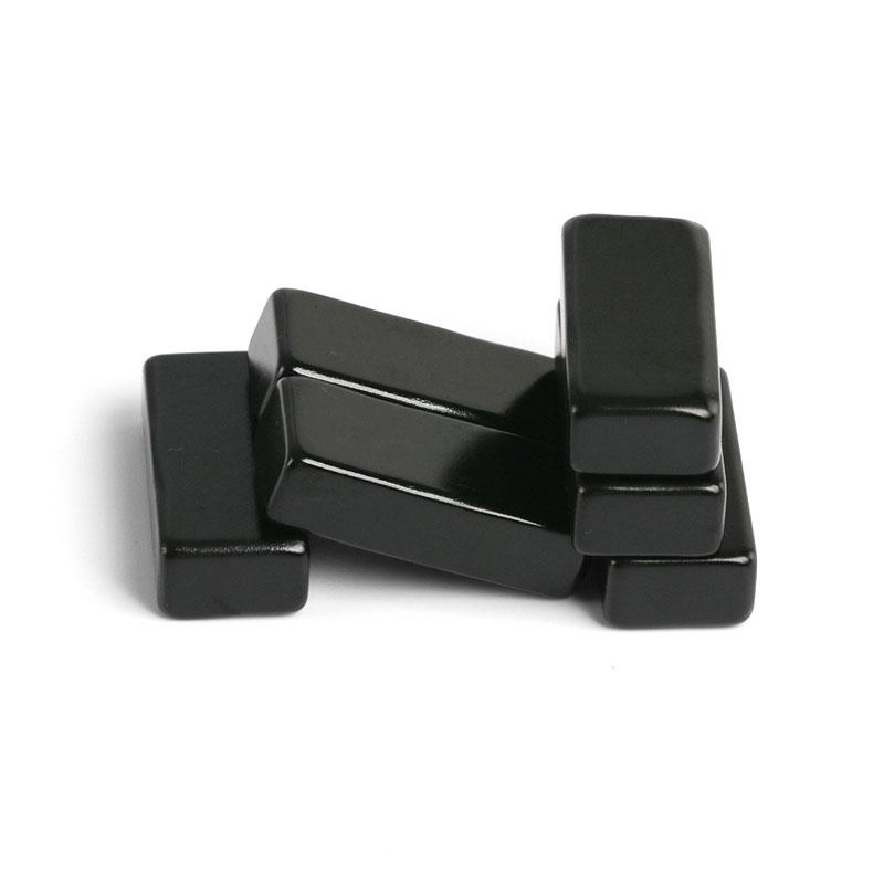
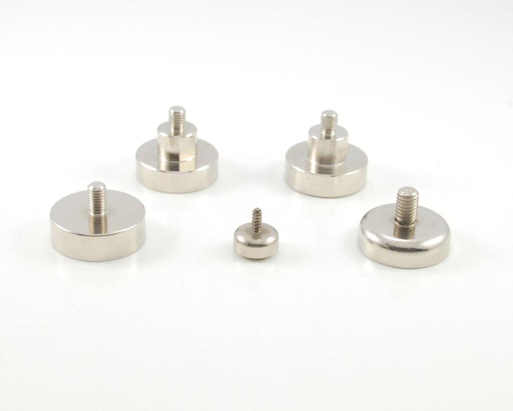
A practical magnetic coupling system includes two magnet rotors, pole carriers or steel back iron, a nonmagnetic separation wall, bearings or bushings, shafts or cams, and mechanical stops. NdFeB is common because the lock envelope is small. High-coercivity grades may be needed near a motor winding or where the mechanism can become hot. SmCo can be evaluated for higher temperature or improved corrosion stability.
The barrier should be nonmagnetic and as thin as structural, wear and sealing requirements allow. Austenitic stainless steel, engineering polymers and other low-permeability materials are typical candidates. Ferromagnetic steel in the gap can divert flux and reduce usable torque. Conductive metal barriers can also produce eddy-current drag at high speed, although lock speeds are normally low.
Design Variables That Control Torque
| Variable | Effect | Engineering check |
|---|---|---|
| Axial or radial air gap | Larger gap sharply reduces torque | Include barrier, coatings, runout and assembly tolerance |
| Magnet grade and volume | Changes available air-gap flux | Use hot B-H data, not only room-temperature Br |
| Number of pole pairs | Changes torque profile and pole pitch | Balance peak torque, smoothness and assembly complexity |
| Back-iron thickness | Controls return-path saturation | Increase only where simulation shows saturation |
| Angular and radial alignment | Misalignment reduces torque and adds bearing load | Define concentricity, runout and end play |
| Temperature | Reduces magnet flux and may soften plastics | Test hot unlock torque and cold friction |
| External magnetic field | May bias sensors or magnetic elements | Evaluate shielding and tamper scenarios |
Security and Failure-State Engineering
A magnetic coupling is a motion-transfer component, not the authentication method. The electronic lock still needs secure credential validation, position sensing, control logic and a defined fail-safe or fail-secure state. The mechanism should be tested against external magnets, impact, vibration, forced knob rotation, a stalled bolt, power loss and repeated slip.
Magnetic encoders, Hall sensors and reed switches may share the same enclosure. The coupling’s leakage field can shift their switching point, so sensor placement and shielding should be validated on the complete assembly. A good design maps the magnetic field in every latch position rather than testing each component separately.
Prototype and Production Validation
Measure static breakaway torque, running torque, peak coupling torque, angular backlash, slip behavior, temperature rise and cycle life. Repeat the test at minimum and maximum gap, tolerance extremes, hot and cold conditions, and after corrosion or ingress testing. The acceptance fixture should reproduce the actual barrier and rotor alignment.
For production, magnet polarity and orientation need poka-yoke controls. Adhesive bondline, press fit, carrier dimensions, concentricity and back-iron thickness should be inspected. A coupling that passes a surface-gauss check can still fail torque because of a wrong pole sequence or excessive gap.
Guande Magnetic Coupling Capability
Guande supports rotor layout, magnet grade, pole count, steel return paths, carrier design, assembly tooling and torque inspection. Our magnetic coupling solutions can be developed around the real barrier thickness and torque envelope. We also provide custom magnet segments and complete custom magnetic assemblies.
When comparing magnetic coupling manufacturers, ask for torque at the specified working gap, temperature and alignment—not only magnet grade. Send the lock envelope, latch torque curve, barrier material, duty cycle and fail-state requirements through our engineering quote form for a design review and prototype plan.