A magnetic unlocking mechanism is a purpose-built latch that responds to a matched magnetic key or actuator without a direct mechanical connection through the panel. In legitimate products, the internal latch, magnet pattern, spring, travel and housing are designed together. Common examples include child-safety cabinet locks, retail display fixtures, authorized service panels and removable equipment covers.
Scope and safety: this article concerns OEM magnetic release mechanisms designed by or for the equipment owner. It does not provide instructions for bypassing door locks, safes, anti-theft devices or third-party security systems.
Core Working Principle
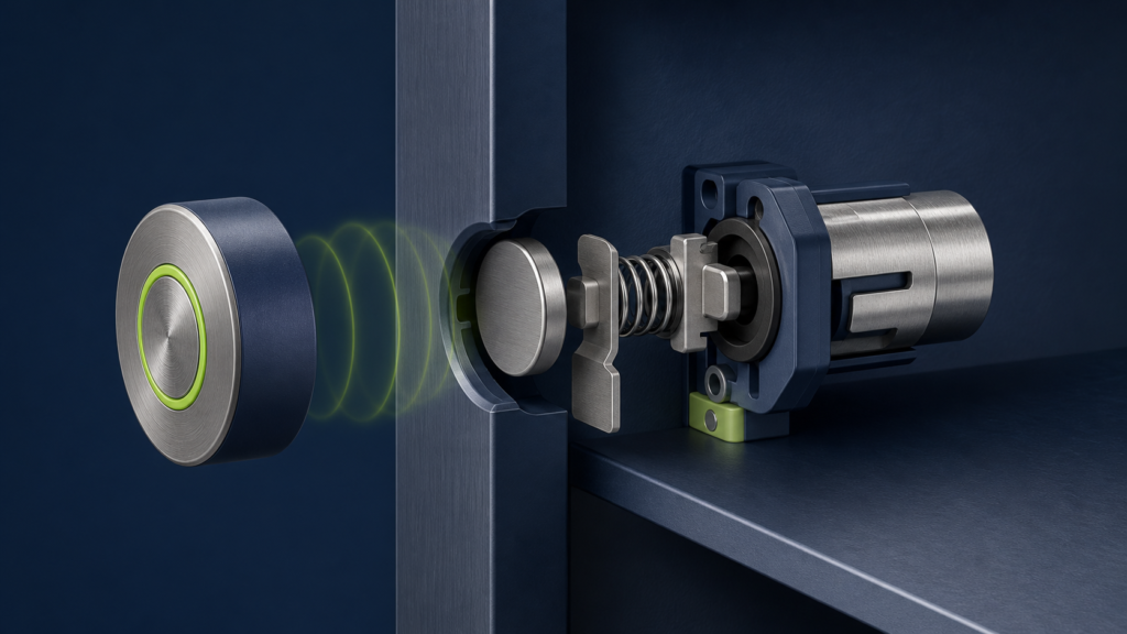
The external magnetic key produces a field through a nonmagnetic panel such as wood, polymer, glass or thin nonmagnetic stainless steel. Inside, that field acts on a magnet, steel armature or magnetically biased slider. The resulting force or torque moves a latch against a return spring. Once the key is removed, the spring returns the latch to its default state.
The mechanism succeeds only if magnetic force at the working gap exceeds spring preload, friction, seal drag and any load applied to the latch. The available margin must still cover panel-thickness tolerance, key placement error, temperature and production variation.
Typical Components
| Component | Function | Critical design variable |
|---|---|---|
| External magnetic key | Provides the release field | Magnet grade, pole pattern, yoke, grip and alignment feature |
| Internal armature or magnet | Converts field into motion | Material, area, stroke, orientation and residual attraction |
| Latch / slider | Retains or releases the panel | Load direction, engagement depth and wear |
| Return spring | Sets the default locked or released state | Preload, rate, fatigue and temperature |
| Housing and guides | Controls travel and alignment | Friction, molding tolerance, debris and impact |
| Panel interface | Defines the magnetic air gap | Thickness, material, curvature and hidden installation tolerance |
Attraction, Repulsion and Rotational Release
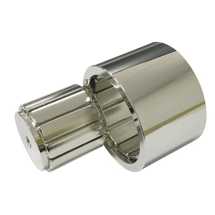
Three architectures are common in legitimate magnetic latch design. An attraction design pulls a steel armature or internal magnet toward the key. A repulsion design pushes a like pole away, but requires controlled orientation. A rotational design applies torque to a magnetized cam or rotor and can provide a defined release stroke.
| Architecture | Advantage | Design concern |
|---|---|---|
| Magnet-to-steel attraction | Simple and tolerant of key polarity | Residual sticking and response to unrelated strong magnets |
| Magnet-to-magnet attraction | Higher force in a compact volume | Polarity, assembly orientation and impact load |
| Magnetic repulsion | Can create clean separation motion | Alignment sensitivity and lateral instability |
| Rotating magnetic cam | Converts field direction into torque | More components, tolerance and wear |
| Multipole matched key | Rejects some simple uniform-field actuators | Greater key and assembly complexity |
Why Working Distance Dominates the Design
The cabinet wall, decorative finish, adhesive, air clearance and housing all add to the magnetic gap. Field and force fall rapidly with distance, especially for small magnets. A design that works on a 12 mm panel may fail after a thicker door, curved surface or installation offset is introduced.
Increasing magnet grade is not always the best correction. A larger pole area, steel yoke, reduced gap, different armature geometry or lower-friction guide can produce a more stable result. The external key must also be safe to handle and mechanically robust.
Conceptual Force Budget
The mechanism should satisfy a simple release condition:
Fmagnetic,min > Fspring,max + Ffriction,max + Fseal + Fload component + margin
This is a system requirement, not a catalog pull-force comparison. Catalog pull force is usually measured in direct contact with thick steel. A magnetic release latch operates through a gap, with small moving parts and changing geometry. Prototype force-versus-distance data is therefore essential.
Legitimate Application Scenarios
| Application | Why magnetic release is useful | Safety boundary |
|---|---|---|
| Child-safety cabinet lock | Hidden hardware and no exposed keyway | Adult access, emergency opening and entrapment risks must be evaluated |
| Retail display fixture | Clean appearance and authorized staff access | Not a substitute for certified theft protection |
| Service access panel | Tool-free opening by trained technicians | Do not use where hazardous energy requires a compliant lockout |
| Removable machine cover | Fast maintenance with concealed hardware | Guarding regulations may require interlocks or fasteners |
| Furniture and exhibition systems | Invisible latch and repeatable alignment | Load, pinch and accidental release must be tested |
| Sealed consumer enclosure | No mechanical penetration through the outer wall | Ingress protection must be validated independently |
Multipole and Coded Magnetic Keys
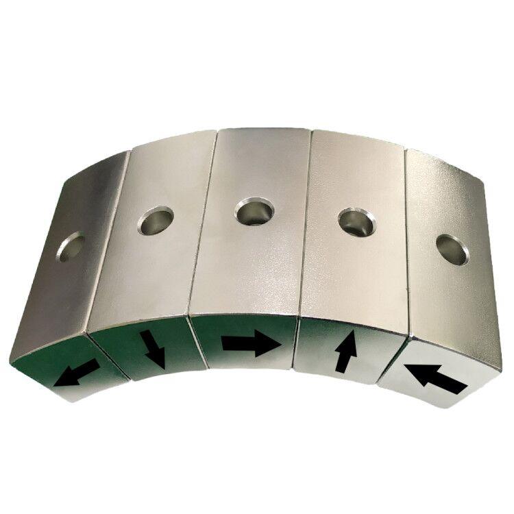
A matched key can use several magnets with defined positions and directions. The internal magnetic assembly responds to the combined field pattern rather than one simple pole. This can reduce accidental actuation and improve alignment.
However, a multipole pattern should not be marketed as high-security encryption. Strong external fields, manufacturing tolerance and field overlap can produce unintended responses. Applications requiring certified security should use approved mechanical or electronic access-control systems.
Material and Environmental Choices
Sintered NdFeB magnets offer high force in a compact key. Ferrite may suit larger, lower-cost products. SmCo can be considered for higher temperature or improved corrosion stability. The housing may use engineering plastic, stainless steel or coated steel, while the armature needs predictable magnetic permeability and corrosion protection.
Temperature affects magnet output, spring force, plastic dimensions and lubricant. Humidity can attack exposed NdFeB and steel. The magnet should be coated or encapsulated, and the complete assembly tested after environmental conditioning.
Design Verification Checklist
- Measure release force and stroke at minimum and maximum panel thickness.
- Test key placement error in two axes and angular misalignment.
- Check hot and cold operation, humidity, drop, vibration and cycle life.
- Confirm that ordinary household magnets do not cause unacceptable release.
- Evaluate residual attraction, spring fatigue and debris sensitivity.
- Inspect magnet orientation, bonding, yoke dimensions and moving-part friction.
- Define a safe failure state and manual service procedure.
Guande’s Custom Magnetic Assembly Support
Guande can develop a custom magnetic assembly for authorized OEM release products, including magnet grade and shape, pole pattern, steel yoke, armature interface, bonding fixture, polarity verification and force-at-distance testing. For compact mechanisms, disc magnets or block magnets can be matched to the available envelope.
Where sensing or electronic confirmation is needed, the magnetic sensor assembly and latch should be evaluated together so that the actuation field does not saturate or mis-trigger the sensor. Send the authorized product drawing, panel material, working gap, spring load and environmental requirements for a design review.
Frequently Asked Questions
Can a magnetic latch work through steel?
Ferromagnetic steel redirects and shields the field, so a design intended for wood or plastic will not behave the same way. A dedicated magnetic circuit or another actuation method may be required.
Is a stronger magnet always safer?
No. Excess force can increase pinch risk, attract metal debris, damage components and make accidental interaction with nearby products more likely.
Can this principle replace a certified security lock?
No. It is appropriate for purpose-built latches and controlled access features. Certified security, life-safety and hazardous-energy applications require systems designed and approved for those standards.