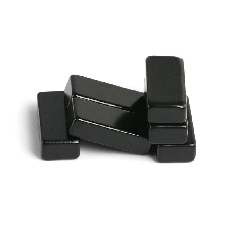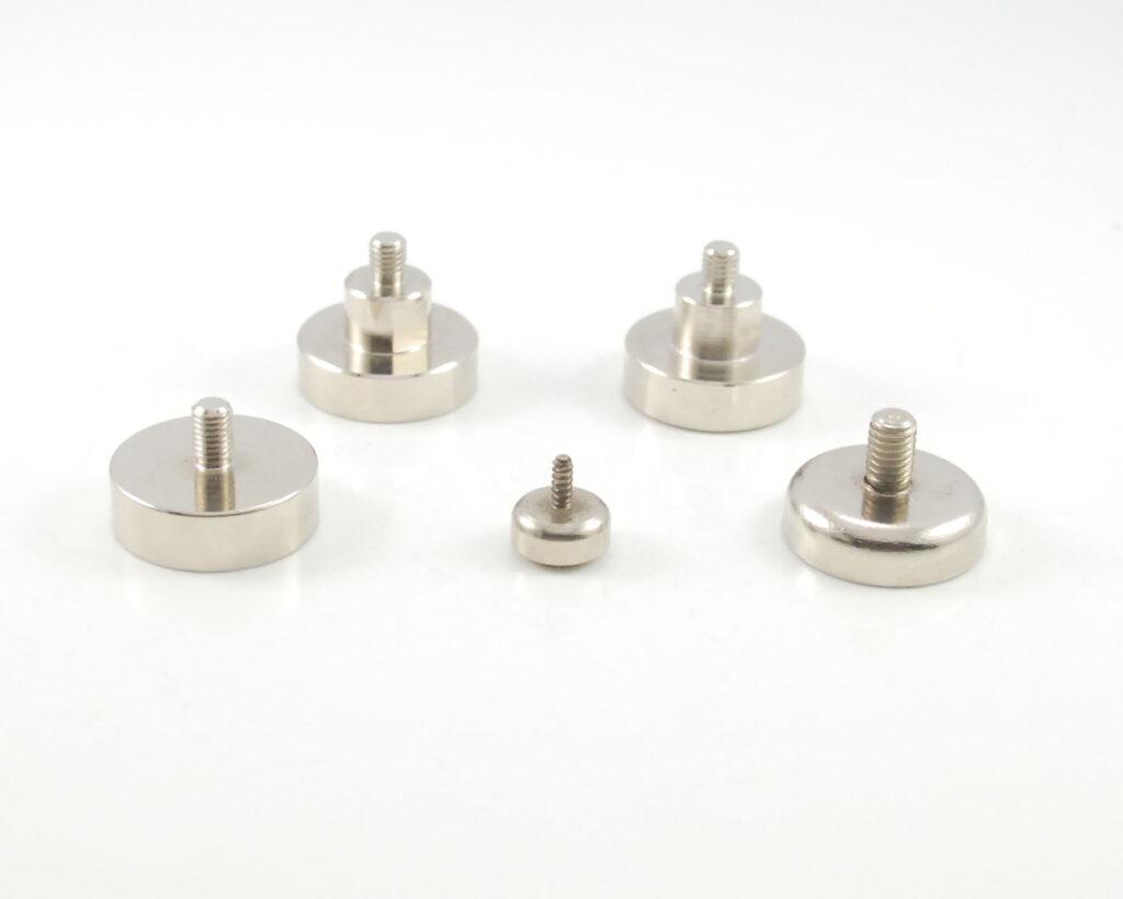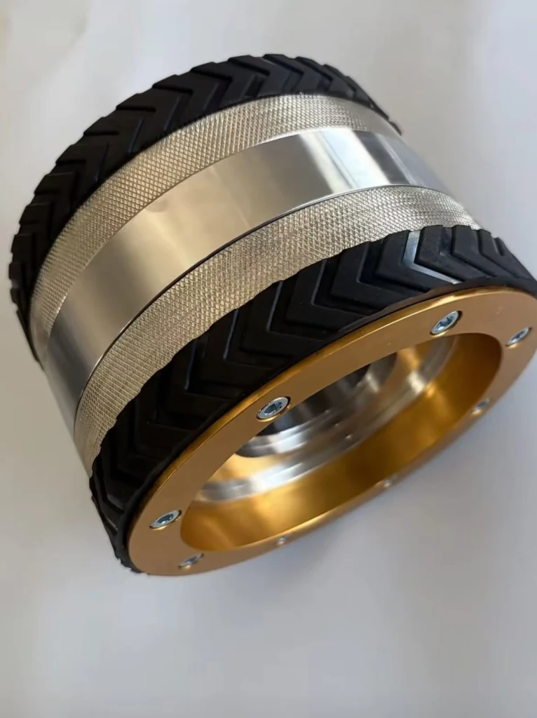
Magnetic wheels allow a mobile robot to travel on ferromagnetic tanks, ship hulls, bridges, towers and pipelines without a separate vacuum system. Each wheel combines a permanent-magnet circuit with a mechanical tread. The magnetic circuit supplies normal force toward the steel surface, while tread friction converts motor torque into climbing traction.
Design rule: holding force and driving force are different. A wheel can have high static pull in a laboratory test but still slip, detach at an edge or overload its drivetrain in service.
How a Magnetic Wheel Produces Adhesion
Many designs place axially magnetized NdFeB rings or discs between low-carbon-steel pole pieces. The steel redirects flux from the magnet faces toward alternating poles at the tread. When the wheel approaches a steel plate, the target closes the magnetic circuit. This reduces reluctance and creates attractive force across the working gap.
The complete magnetic assembly determines performance. Magnet volume alone is not enough: pole width, yoke saturation, target thickness, wheel diameter, tread material, coating gap and curvature all shape the useful flux.
Adhesion, Traction and Required Safety Margin
On a vertical wall, the robot weight acts downward while magnetic force acts toward the wall. The maximum ideal traction is approximately the coefficient of friction multiplied by the total normal force. Real systems need margin for cable drag, acceleration, joint gaps, dust, water, curvature and unequal wheel loading.
| Quantity | Engineering meaning | Common mistake |
|---|---|---|
| Normal adhesion force | Force pulling the wheel toward steel | Using it directly as vertical payload |
| Available traction | Friction-limited force along the surface | Ignoring wet or coated steel |
| Detachment moment | Peeling load caused by robot geometry | Testing only straight pull |
| Drive torque | Torque needed for weight, rolling loss and obstacles | Ignoring magnetic drag and seal friction |
| Safety factor | Margin for worst credible condition | Applying one factor to every load mode |
Air Gaps Reduce Holding Force Quickly
Paint, rust, rubber tread, weld scale and surface waviness form an air gap. Because air has much higher magnetic reluctance than steel, even a small additional gap can cause a large drop in force. The wheel should be evaluated at the maximum real gap, not only on a clean ground plate.
A rubber or polyurethane tread improves friction and protects the surface, but it also separates the poles from the steel. Some designs expose steel pole rims beside a thin tread; others accept lower magnetic force for better traction and wear. The best choice depends on the robot’s load and inspection environment.
Curved Tanks and Pipes
A flat pole profile does not contact a small-radius pipe evenly. The effective gap grows at the edges, reducing adhesion. Narrow wheels follow curvature better but may need more wheels to carry the load. A crowned or segmented pole profile can help, provided the magnetic path remains continuous and the tread does not create unstable steering.
| Surface condition | Main risk | Design response |
|---|---|---|
| Flat painted plate | Coating gap | Test at maximum paint thickness |
| Small-radius pipe | Reduced pole contact | Narrow or contoured wheel |
| Weld seam | Momentary gap and impact | Compliant suspension and multiple contact points |
| Wet or oily steel | Low friction | Tread compound and drainage pattern |
| Thin steel wall | Target saturation | Measure force on actual thickness |
Robot Layout and Transition Stability
A four-wheel magnetic wheel robot should not assume equal force at every wheel. Frame stiffness, suspension travel and surface geometry redistribute load. At a convex transition or obstacle, one wheel may lose contact while another becomes the pivot. The center of gravity should remain close to the wall to reduce peeling moment.
For floor-to-wall or wall-to-ceiling transitions, articulated wheel modules or a compliant chassis are often required. The control system should limit acceleration and monitor wheel speed, motor current or adhesion sensors for early slip detection.
Motor and Bearing Considerations
High adhesion increases rolling resistance and bearing load. Gearmotors must overcome gravity, magnetic attraction, tread deformation and seal drag. The shaft and hub should carry radial load without changing the critical air gap inside the wheel. Bearings need protection from abrasive dust, water and magnetic particles.
Why Wheel Force Must Be Measured as an Assembly
A magnetic adhesion wheel cannot be accepted from magnet certificates alone. Steel permeability and pole-piece flatness affect the usable circuit, while adhesive thickness, hub runout and tread concentricity change the working gap as the wheel rotates. A practical end-of-line test records pull force at defined gaps and checks running torque through a full revolution. Polarity verification is also necessary because one incorrectly oriented magnet can create a local weak zone that appears only at a particular wheel angle.
What to Specify for a Climbing-Robot Wheel
| Input | Why it is needed |
|---|---|
| Robot mass and payload | Sets static and dynamic load |
| Number and location of wheels | Defines load distribution and peeling moment |
| Steel grade and thickness | Controls magnetic return-path capability |
| Paint, rust and maximum gap | Determines real adhesion |
| Minimum curvature and obstacles | Defines wheel width and suspension |
| Speed, acceleration and duty cycle | Sets drive torque and thermal load |
| Environment | Guides coating, tread, sealing and temperature grade |
Validation Tests
We recommend pull force versus gap, shear traction on dry and wet surfaces, rolling torque, obstacle crossing, curved-surface adhesion, thermal operation and endurance cycling. Detachment should be tested in the actual robot geometry because straight-pull fixtures do not reproduce peeling moments. A secondary restraint is appropriate during development and whenever detachment could create a hazard.
Guande Magnetic-Wheel Development Support
We support wheel-level magnetic-circuit design, NdFeB grade selection, steel pole machining, bonding, controlled assembly and inspection. Related references include our guide to axially magnetized magnetic wheels, the comparison of contact and non-contact magnetic wheels, and our custom magnetic assembly capability.
Provide the robot mass, wheel envelope, target steel, gap, curvature, speed and safety requirement through Get a Quote. We will propose a prototype test plan together with the wheel design.