A magnetic wheel designed to run directly on a steel surface is not the same product as a magnetic wheel designed to transmit torque across an air gap or sealed wall. Both may contain NdFeB magnets, steel pole pieces, a hub, and bearings, but their flux paths, pole patterns, mechanical loads, and acceptance tests are different.
Design rule: first define whether the wheel must create normal holding force on a steel track or transfer rotational torque to a separate follower. Do not reuse one magnetic circuit for the other function without recalculation.
Two Different Working Principles
| Direct-contact adhesion wheel | Non-contact magnetic transmission wheel |
|---|---|
| Wheel pole → tread gap → steel surface → return pole | Driver pole → air/barrier gap → follower pole |
| Primary output: normal holding force | Primary output: transmitted torque |
| Traction comes from tread friction under magnetic normal load | Follower rotates through attraction and repulsion between pole patterns |
| Target steel closes the magnetic circuit | A second magnetic rotor closes or couples the field |
Direct-Contact Magnetic Wheel Design
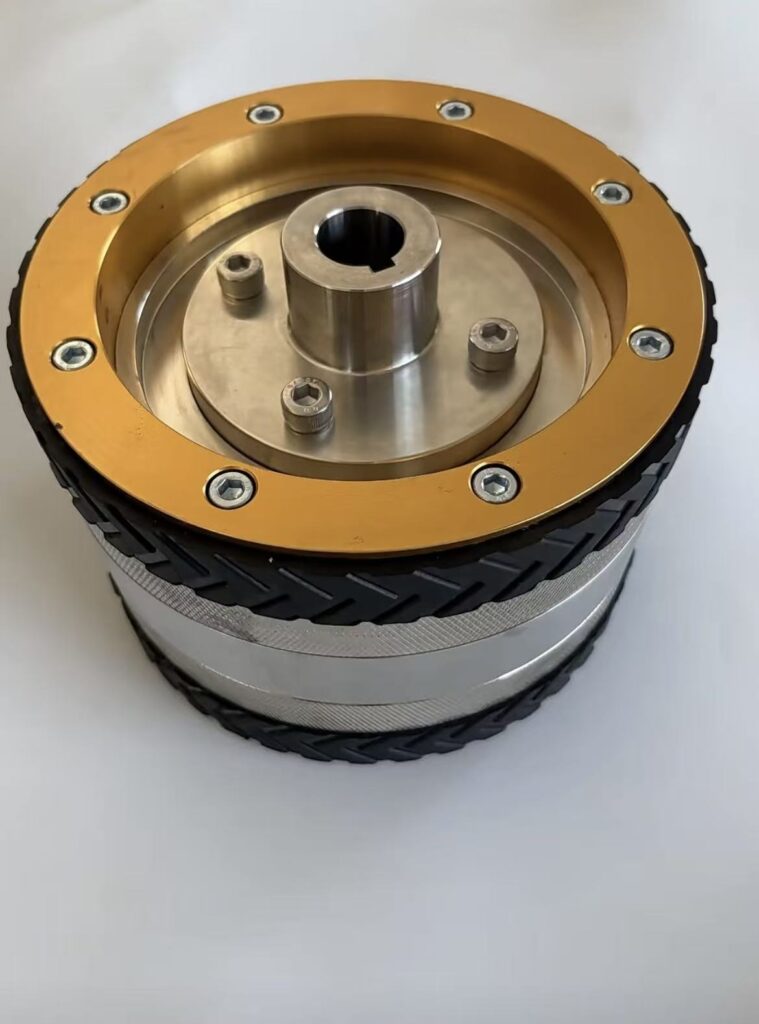
Direct-contact wheels are used on steel tanks, ship hulls, bridges, pipelines, and inspection robots. An axially magnetized ring or disc magnet is often placed between low-carbon-steel pole pieces. The pole pieces redirect flux from the magnet faces toward the tread. The steel surface then completes the return path.
The magnetic force presses the wheel against the surface. Available tangential traction is approximately related to the friction coefficient multiplied by the normal load, but real performance also depends on tread deformation, surface contamination, curvature, and load transfer between wheels.
Critical direct-contact parameters
- Effective working gap: rubber thickness, paint, rust, debris, and local surface roughness all add magnetic gap.
- Target material: steel grade, thickness, saturation, and backing structure affect the return path.
- Surface curvature: pipe diameter and hull curvature change contact area and pole-to-steel distance.
- Load direction: normal pull, shear traction, peel moment, and obstacle impact require separate checks.
- Tread: softer rubber may improve friction but increases the magnetic gap and rolling resistance.
- Safety factor: calculate with the worst wheel unloading, cable force, acceleration, and surface condition.
Non-Contact Magnetic Transmission Design
A non-contact magnetic wheel transfers rotation to a follower without touching it. The driver and follower use alternating magnetic poles. As the driver rotates, the field pulls the follower poles into a new alignment. Below the pull-out torque, the follower rotates synchronously with a load-dependent angular offset.
The arrangement can be radial, axial-face, or linearized around the circumference. A coaxial cylindrical design usually uses multipole patterns facing across a radial gap. Two facing discs normally use circumferentially alternating axial poles across an axial gap. The pole count and magnetization direction must match the geometry.
Critical non-contact parameters
- Continuous, startup, peak, and jam torque.
- Radial or axial working gap, including barrier thickness and tolerance.
- Pole count, magnet arc, pole pitch, and relative phase.
- Driver and follower diameter, active length, and back-iron saturation.
- Speed, dynamic balance, angular misalignment, and bearing stiffness.
- Magnet temperature and demagnetization margin during overload.
- Barrier conductivity and possible eddy-current heating.
The design principles overlap with our permanent magnetic coupling capabilities, especially where torque passes through a sealed containment wall.
Why the Air Gap Changes Both Designs Differently
Magnetic field and force fall rapidly as the working gap increases. In a direct-contact wheel, the gap is usually created by the traction layer and surface condition. Increasing tread thickness may improve durability but reduce holding force.
In a non-contact drive, the gap is intentional and must include assembly clearance, shaft runout, barrier thickness, and thermal expansion. A larger gap reduces transmitted torque and may require more magnet volume, a larger diameter, or a different pole count. Gap tolerance can also change torque ripple and pull-out behavior.
| Design item | Direct contact | Non-contact transmission |
|---|---|---|
| Main calculation | Holding force and traction margin | Torque-angle curve and pull-out torque |
| Typical pole location | At or near the outer tread | Facing the follower rotor |
| Mechanical priority | Tread grip, obstacle crossing, impact | Concentricity, balance, barrier clearance |
| Failure mode | Slip or detachment from steel | Loss of synchronization or excessive heat |
| Primary test | Normal pull and driven traction on target surface | Static/dynamic torque across specified gap |
Magnetization and Pole-Piece Differences
Direct-contact wheels often use axially magnetized rings because steel pole pieces can redirect the flux to the tread efficiently. This simplifies magnet manufacture and produces robust alternating pole shoes at the contact surface.
Non-contact designs more often require a true multipole pattern around a cylindrical or disc interface. The designer may use individual blocks, arc segments, multipole rings, or a Halbach arrangement. Pole-angle tolerance and magnet orientation have a direct effect on torque ripple and usable coupling torque.
Mechanical Design Cannot Be Separated from the Magnetic Circuit
For a climbing wheel, the hub, bearings, tread, pole shoes, and fasteners must survive impact while keeping the magnetic gap stable. The magnet should not carry structural impact loads. For a non-contact drive, sleeves, adhesives, and hubs must retain magnets against centrifugal force and thermal cycling while maintaining runout.
Conductive stainless-steel or metal barriers can create eddy-current loss in high-speed non-contact systems. The shell material and thickness must therefore be included in magnetic and thermal analysis rather than added after the rotor is designed.
Recommended Validation Plan
| Stage | Direct-contact wheel | Non-contact wheel |
|---|---|---|
| Component | Dimensions, magnetization, coating, tread hardness | Dimensions, pole orientation, flux, rotor runout |
| Bench | Pull force on specified steel and gaps | Torque-angle and pull-out torque by gap |
| Dynamic | Traction, rolling resistance, obstacle crossing | Speed, balance, temperature rise, decoupling |
| Environment | Paint, rust, water, contamination, curvature | Temperature, pressure barrier, media, vibration |
Guande Design and Production Support
Guande supports NdFeB selection, magnetic-circuit simulation, steel pole-piece design, custom hubs, magnet-to-metal bonding, tread integration, and magnetic inspection. For projects that combine magnets, machined steel, adhesives, and mechanical retention, our custom magnetic assembly workflow keeps the magnetic and mechanical tolerances in one controlled plan.
We communicate practical limits early: target-surface data for direct-contact wheels, or torque, gap, speed, and barrier data for non-contact designs. This avoids optimizing a catalog pull-force value that does not represent field use.
Frequently Asked Questions
Can the same magnetic wheel work in contact and across a gap?
It may produce some force in both situations, but it will rarely be optimized for both. Direct-contact holding and non-contact torque require different pole interfaces, measurements, and safety factors.
Does thicker rubber always improve a climbing wheel?
No. It may improve grip and wear resistance, but it increases magnetic gap and can reduce holding force. Tread compound and thickness must be tested together with the magnetic circuit.
What sets the maximum non-contact torque?
Magnet properties, rotor diameter, active length, pole count, working gap, barrier, back iron, temperature, and alignment all contribute. The final value should be confirmed with a torque-angle test.
Share your wheel envelope, target surface or transmission gap, load, speed, and operating environment for a direct and efficient feasibility review.