The low-carbon-steel cup in a pot magnet is an active magnetic-circuit component, not just a protective shell. Its back plate and wall must carry flux from one pole of the magnet to the annular pole at the working face. If the steel is too thin, it approaches saturation, magnetic reluctance rises and more flux leaks behind or around the assembly. Increasing thickness helps only until the return path carries the available flux with adequate margin.
Design rule: cup thickness should be sized from flux and allowable steel induction—not selected as a fixed percentage of magnet diameter.
What the Steel Cup Does
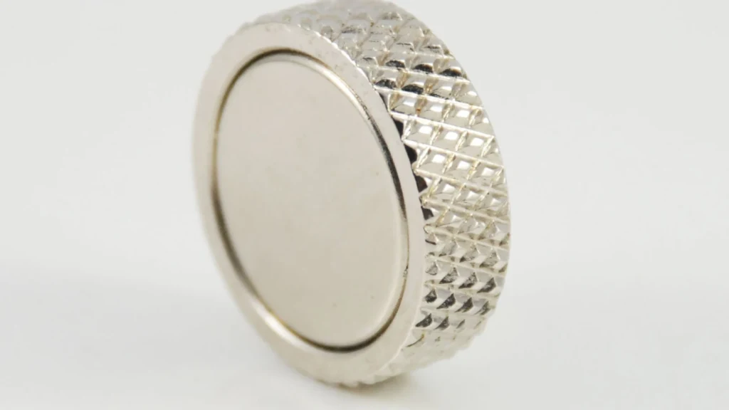
In a common pot magnet design, a disc or ring magnet sits inside a low-carbon-steel cup. The rear pole connects to the cup, while the exposed magnet face and front steel rim present opposite poles close together. A ferromagnetic target bridges those poles and closes a short magnetic circuit. This produces high contact force and lower stray field behind the assembly compared with a bare magnet.
The cup has three important sections: the bottom or back plate, the cylindrical wall and the front annular pole. Each section can become the limiting cross-section. A thick bottom with a narrow wall does not solve wall saturation; a generous wall with a thin annular rim can still choke flux at the working face.
| Cup section | Magnetic function | Typical risk when too thin |
|---|---|---|
| Bottom plate | Collects flux from the rear magnet pole | High induction, rear leakage and uneven pole loading |
| Side wall | Carries flux toward the front rim | Localized saturation and leakage outside the cup |
| Front annular pole | Transfers return flux into target steel | Small effective area and early target/pole saturation |
| Central bush or hole region | Provides mounting while preserving circuit area | Flux crowding around countersink, thread or weld |
Why Thin Steel Reduces Holding Force
Magnetic flux density is approximately flux divided by cross-sectional area. When the back plate is thinned, the same flux must pass through less steel area, so induction rises. Low-carbon steel has high permeability below saturation, but permeability falls sharply as the material approaches its knee. The saturated section behaves like added reluctance and pushes flux into leakage paths.
Useful pot magnet holding force depends on flux density across the actual target interface. An idealized pressure relationship, F ≈ B²A/(2μ₀), shows why a modest reduction in interface B can create a larger reduction in force. Real assemblies also include fringing, surface roughness, pole spacing and target saturation, so finite-element analysis or a controlled pull test is preferred.
Why Thicker Steel Eventually Stops Helping
Once the cup works below a suitable induction limit, extra thickness yields diminishing returns. Flux is then limited by magnet operating point, working-face area, target material, air gap or another steel section. A thicker bottom may also consume axial space that could have been used for a thicker magnet, increase mass and cost, or deepen a countersunk feature that disturbs the circuit.
| Thickness condition | Magnetic behavior | Likely design result |
|---|---|---|
| Clearly undersized | Return path saturates | Low force, high leakage and sensitivity to tolerance |
| Near the knee | Small changes create nonlinear effects | Lot-to-lot force variation and hot-performance risk |
| Adequate margin | Steel carries flux efficiently | Stable force with balanced mass and size |
| Oversized | Other circuit elements limit flux | More weight/cost with little force gain |
Material Grade Matters as Much as Thickness
Use low-carbon steel with predictable permeability and saturation behavior. Stainless steel is not automatically suitable: austenitic grades may carry little magnetic flux, while ferritic or martensitic grades have different permeability and corrosion trade-offs. Heat treatment, plating and cold work can also affect properties. The drawing should specify material, not only “steel cup.”
For a steel cup magnet, machining tolerance matters at the same scale as nominal thickness. A deep countersink, eccentric bore or thin plated edge can reduce the minimum magnetic section below the drawing average. Evaluation should use minimum-material dimensions, including coating allowance and any radius or forming thinning, because local saturation begins at the narrowest effective path.
Interactions with Magnet and Target Geometry
A higher Br magnet can drive the cup closer to saturation. A larger central hole removes magnet volume and changes flux distribution. A thin target plate may saturate before the cup, so increasing cup thickness will not improve pull. Paint, rubber or adhesive creates an air gap, lowering interface B. The previous guide How Pot Magnets Work explains these system effects.
| Design variable | Effect on cup-thickness decision | Recommended verification |
|---|---|---|
| Magnet grade/thickness | Changes available flux and cup saturation risk | Load-line and steel-induction review |
| Mounting hole/thread | Removes steel and crowds flux | Section analysis around the feature |
| Target thickness | May become the real saturated element | Pull test on production-equivalent target |
| Coating or rubber gap | Reduces interface field | Test at maximum compressed gap |
| Temperature | Lowers magnet Br and adhesive capability | Hot pull and retention test |
A Practical Optimization Method
- Define target steel, thickness, surface condition, gap and load direction.
- Set the maximum cup envelope and mounting feature.
- Estimate flux and check bottom, wall and front-pole cross-sections.
- Simulate at minimum material dimensions and highest/lowest relevant temperature.
- Prototype at least two cup thicknesses around the predicted transition.
- Measure direct pull with the same plate, speed and separation method.
- Verify shear, peeling moment, impact and corrosion separately where relevant.
Pull testing should specify plate material, thickness, surface finish, separation speed and loading direction. A result from a polished laboratory block should not be transferred directly to painted sheet or a curved machine surface. Record both average and minimum lot force; cup-thickness optimization is successful only when it improves production margin, not merely the best prototype result.
Guande Pot Magnet Capability
Guande combines NdFeB disc magnets, low-carbon-steel cups, mounting features, coating and controlled bonding. Our custom magnetic assemblies can be reviewed for steel saturation, air-gap sensitivity and production pull-force inspection. We develop custom pot magnets around the real target rather than a catalog diameter alone.
Send the envelope, target steel, working gap, required load, temperature and mounting detail through Get a Quote. We will compare cup sections and test conditions before fixing the production drawing.