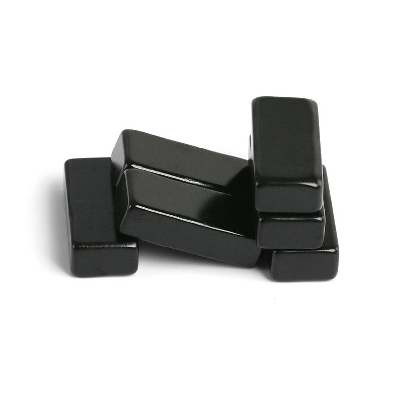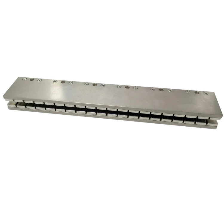
A permanent-magnet linear motor track is usually built from repeated NdFeB blocks or segments bonded to a steel back iron or nonmagnetic carrier. The magnets may be magnetized before assembly, or unmagnetized parts may be assembled first and pulsed afterward. Neither route is universally better. Pole pitch, pattern, track length, magnet coercivity, fixture energy, handling force and inspection access determine the practical choice.
Production principle: select the magnetization route before finalizing the mechanical drawing; it changes fixture access, adhesive process, safety controls and allowable track length.
What a Linear Motor Magnet Track Must Control
Alternating N-S poles create a spatial field waveform that interacts with the driven coil. Thrust constant, cogging, ripple and encoder behavior depend on consistent pole pitch, magnet position, air gap and magnetic output. Some tracks use simple alternating blocks; others use angled or transverse segments in a Halbach arrangement to strengthen the working side and reduce rear leakage.
The steel back iron returns flux and supports the array, but it can attract every pre-magnetized block with high force. For a long linear motor magnet assembly, accumulated tolerances and magnetic interactions make manual placement unsafe and inconsistent without dedicated tooling.
| Architecture | Typical pole arrangement | Assembly implication |
|---|---|---|
| Single-sided iron-core track | Alternating axial blocks on steel | Strong attraction to back iron; simple polarity map |
| Double-sided track | Opposed tracks around a coil | Gap and facing-pole relationship require matched fixtures |
| Halbach track | Rotating magnetization vectors | More orientations and higher segment-repulsion forces |
| Ironless U-channel | Two rows creating a controlled gap | Parallelism and cross-track field symmetry are critical |
Method 1: Assemble Pre-Magnetized Magnets
This is the most common route for long tracks and high-Hcj linear motor magnets. Each block is saturated in a standard fixture, then verified for polarity and magnetic moment before bonding. The assembly fixture controls spacing and prevents magnets from snapping together or ejecting from the work area.
Advantages include flexible track length, standard magnetizing equipment and the ability to sort magnets before assembly. Challenges are high handling force, adhesive squeeze-out, brittle edge damage and polarity mistakes. Fixtures typically use nonmagnetic stainless steel, aluminum, engineering plastic or controlled steel inserts, with mechanical stops that allow a safe staged release.
Method 2: Assemble Unmagnetized Magnets, Then Magnetize
Unmagnetized blocks are easier to place and bond, especially in a dense array. The complete magnet track assembly is inserted into a custom pulse fixture that creates the required alternating or multipole pattern. This can reduce handling risk and improve positional stability during bonding.
The limitation is fixture feasibility. A long steel-backed track has a large magnetic circuit, high eddy-current load and substantial pulse-energy requirement. The coil must deliver enough field at every magnet to saturate the selected grade. Very long tracks may not fit a practical fixture, and local multipole saturation can be difficult when pole pitch is small or the back iron shunts magnetizing flux.
| Decision factor | Pre-magnetized assembly | Post-assembly magnetization |
|---|---|---|
| Handling force | High; robust insertion fixture required | Low during bonding |
| Track length | Scales well by repeated segments | Limited by magnetizing coil and energy |
| Pole flexibility | Each block can have a defined direction | Fixture must create the entire pattern |
| Sorting before assembly | Easy to measure individual moment | Relies more on material and process consistency |
| Back-iron influence | Creates assembly attraction | Can shunt the magnetizing pulse |
| Repair | Individual segment replacement may be possible | Rework often requires re-pulsing the assembly |
Hybrid and Modular Routes
Long machines often use short qualified modules. Each module can be assembled from pre-magnetized blocks, or post-magnetized if its length fits the fixture. Modules are then installed end-to-end with a controlled phase relationship. This keeps tooling manageable and allows replacement without removing a complete machine-length track.
Adhesive, Surface and Mechanical Retention
Nickel-coated NdFeB and plated steel require cleaning and a validated surface-preparation window. Bondline thickness influences shear stress, thermal expansion and air gap. End stops, cover plates or encapsulation may provide secondary retention. The adhesive must survive peak magnet temperature, acceleration, vibration and coolant exposure—not just room-temperature lap shear.
Assembly sequence should also control cumulative pitch error. A long track built from dozens of magnets can meet individual spacing tolerance while drifting out of electrical phase at the far end. Use fixed datums, module boundaries and independent inspection intervals. Where thermal expansion is significant, allow the carrier to grow without placing brittle magnets or the adhesive joint in peel stress.
| Process control | Why it matters | Typical verification |
|---|---|---|
| Magnet orientation | Wrong pole causes local thrust cancellation | Polarity gauge and fixture poka-yoke |
| Pole pitch/position | Changes waveform and force ripple | CMM, gauges or optical inspection |
| Bondline | Controls retention and magnet height | Witness features, weight or section audit |
| Surface height | Changes motor air gap | Flatness and profile measurement |
| Magnetic output | Confirms pole sequence and uniformity | Hall scan, flux map or force/back-EMF test |
Choosing the Magnetization Method
Use pre-magnetized blocks when the track is long, the grade needs a very high saturation field, individual magnet sorting is important or the pattern uses several discrete directions. Consider post-assembly magnetization for compact modules where handling forces dominate and a validated fixture can saturate every pole. Confirm the choice with a sample module before committing to production tooling.
Whichever route is selected, keep one released polarity master and a signed pole map at the assembly station. Software labels alone are insufficient because magnet direction can be confused when parts are visually identical. A simple incoming polarity check, fixture interlock and final automated scan prevents a wrong-pole module from reaching motor-level testing.
For motor physics and architecture, see How Linear Motors Work and Where They Are Used. Halbach options are covered in Halbach Arrays: Main Structures and Applications.
Guande Assembly and Inspection Support
Guande supplies precision NdFeB block magnets and custom magnetic assemblies. Our work can include grade review, polarity fixtures, controlled insertion, bonding, pole mapping, dimensions and module-level traceability.
Send pole pitch, track section, length, air gap, operating temperature, acceleration and target thrust through Get a Quote. We will compare pre-magnetized, post-magnetized and modular routes before defining tooling.