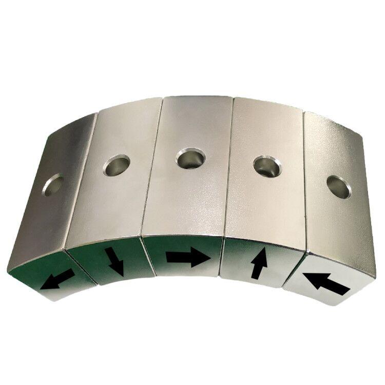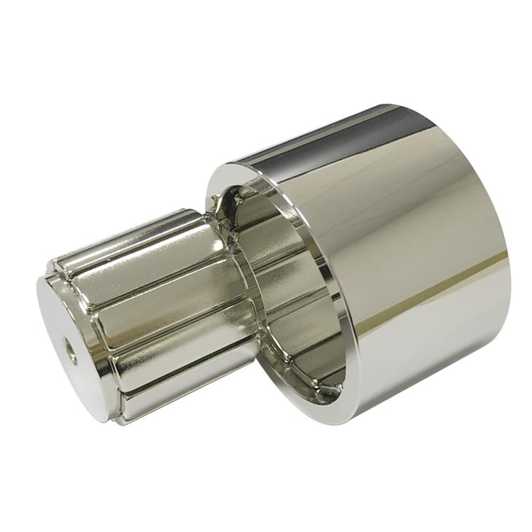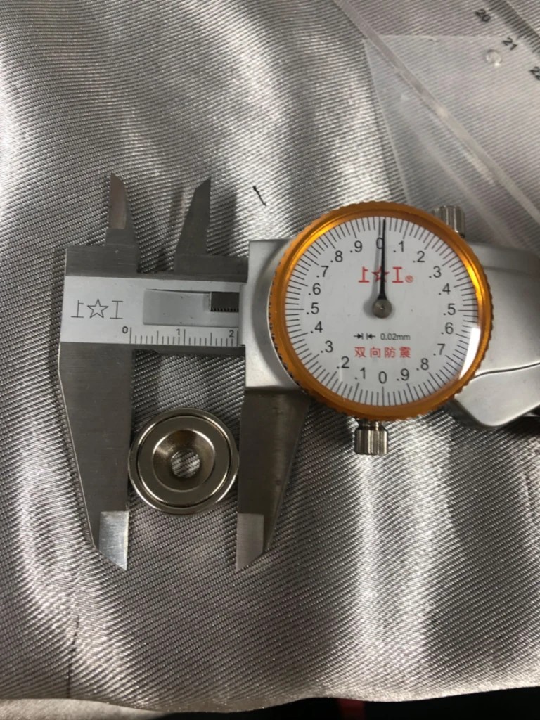
A pot magnet places a permanent magnet inside a ferromagnetic steel cup so that most useful flux is directed toward one working face. The steel protects the sides, provides a mounting body and creates a compact magnetic circuit with high holding force on clean, flat steel. The design does not increase the magnet material’s intrinsic strength; it uses the available flux more efficiently at the contact surface.
Key point: catalog pull force is usually a direct tensile test at zero gap on thick, flat low-carbon steel. Paint, rust, thin sheet, curvature, shear loading and heat can reduce the usable value substantially.
How Do Pot Magnets Work?
In a bare disc magnet, flux leaves one pole, spreads through air and returns to the opposite pole. Air has high magnetic reluctance, so much of the field does not cross the intended target. In a typical pot magnet design, the steel cup contacts one pole around the back and side, carrying flux to an annular pole at the front. The central magnet face forms the other pole. When both front poles touch a steel plate, the target closes the circuit through a short, low-reluctance path.
This concentrated circuit raises the useful flux density at the working face and reduces stray field behind the cup. The cup also helps shield the brittle magnet from side impact. Performance depends on magnet grade and size, cup thickness, pole spacing, target saturation, adhesive layer and dimensional tolerances.
| Component | Function | Design consideration |
|---|---|---|
| Permanent magnet | Supplies magnetomotive force | NdFeB for compact force; ferrite for economy; SmCo for heat/corrosion cases |
| Steel cup | Returns and concentrates flux; protects the magnet | Must carry flux without excessive saturation |
| Nonmagnetic spacer or adhesive | Separates poles and secures the magnet | Gap uniformity affects flux and durability |
| Active pole face | Transfers flux into the target | Flatness and contact area control holding force |
| Mounting feature | Connects the assembly to equipment | Hole, thread or stud must not weaken the magnetic path |
Why a Pot Magnet Holds Strongly in Direct Contact
Magnetic pressure increases approximately with the square of flux density, often expressed as F ≈ B²A/(2μ₀) for an idealized interface. This is not a complete calculation, because leakage, steel saturation, pole shape and fringing remain, but it explains why a small air gap matters so much. Once paint, tape or surface roughness separates the poles from the target, flux density at the interface falls and pull force drops faster than the field alone.
A thin target plate can also saturate and cannot carry all available flux. Austenitic stainless steel may respond weakly or not at all. High-carbon steels, curved surfaces and small contact patches create different working points. Pull force should therefore be verified on the actual counterpart whenever the mount is safety- or alignment-critical.
Main Pot Magnet Types
| Type | Typical mounting | Common use | Important trade-off |
|---|---|---|---|
| Countersunk | Flat-head screw | Fixtures, signs, access panels | Over-tightening can damage the magnet or cup |
| Internal thread | Bolt into rear bush | Sensors, lamps, cameras | Thread depth and torque need limits |
| External stud | Nut or threaded structure | Equipment and temporary stops | Stud weld/bond strength can govern failure |
| Through-hole | Standard bolt | Jigs and machine accessories | Fastener head may reduce active area |
| Rubber-coated | Thread or stud | Painted panels and shear-loaded mounts | Rubber adds a gap but improves friction |
| Hook or eyebolt | Removable attachment | Cables, displays and temporary suspension | Use a safety factor; avoid side loading |
Pull Force Versus Shear Capacity
Pull force is measured perpendicular to the steel surface. A wall-mounted load usually acts in shear, where resistance is approximately the normal magnetic force multiplied by the friction coefficient. Smooth nickel-plated steel may slide well before the published pull rating is reached. Rubber-coated versions increase friction and protect painted surfaces, making them better for vertical mounting even though the rubber gap reduces direct tensile force.
Dynamic shock, vibration and leverage must also be considered. A bracket that extends away from the contact face creates a peeling moment, concentrating the load at one edge. Mechanical retention or two spaced magnets may be more reliable than simply choosing a larger catalog pull value.
Main Pot Magnet Uses
Industrial pot magnet uses include positioning stops, sensor mounts, inspection lamps, temporary machine guards, welding aids, cable routing, removable covers and assembly fixtures. Commercial applications include signs, displays, cameras, retail fittings and access panels. In automation, the compact steel housing makes it easier to integrate a repeatable datum and threaded connection than a bare brittle magnet.
Pot magnets can be used in light lifting only when the complete system is designed and rated for that duty. Never infer a safe working load directly from a laboratory breakaway value. Apply a suitable safety factor and account for target thickness, surface condition, orientation, motion and temperature.
Environmental and Material Selection
| Condition | Likely effect | Practical response |
|---|---|---|
| Paint, coating or contamination | Creates air gap and reduces force | Test at maximum real gap |
| Outdoor humidity or salt | Corrodes cup, magnet or adhesive interface | Specify plating, coating, sealing and validation |
| Elevated temperature | Reduces magnet flux and may weaken adhesive | Select material and adhesive from peak temperature |
| Repeated impact | Chips magnet or loosens bonded parts | Use protective geometry and mechanical retention |
| Thin or curved target | Limits flux path and contact area | Increase target thickness or redesign pole face |
What to Specify for a Custom Pot Magnet
Define the target material and thickness, maximum physical gap, load direction, required working load, temperature, environment, mounting thread and available envelope. Also state whether the acceptance test is direct pull, shear, torque or an assembly function. This information allows custom pot magnets to be optimized around the real interface instead of a nominal magnet diameter.
Guande Design, Assembly and Inspection Capability
Guande combines sintered NdFeB disc magnets with machined or formed steel parts, controlled bonding and application-specific mounting features. Our custom magnetic assemblies can be reviewed for steel saturation, pole geometry, corrosion protection, adhesive selection and assembly tolerance.
Inspection can include dimensions, coating, visual condition, direct pull on a defined test plate and lot-based magnetic checks. Send the target details, force direction, environment, annual volume and drawing through Get a Quote. We will propose a practical structure and a test method that reflects the actual application.