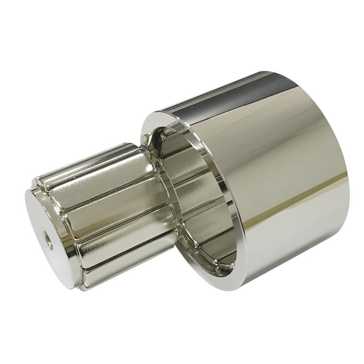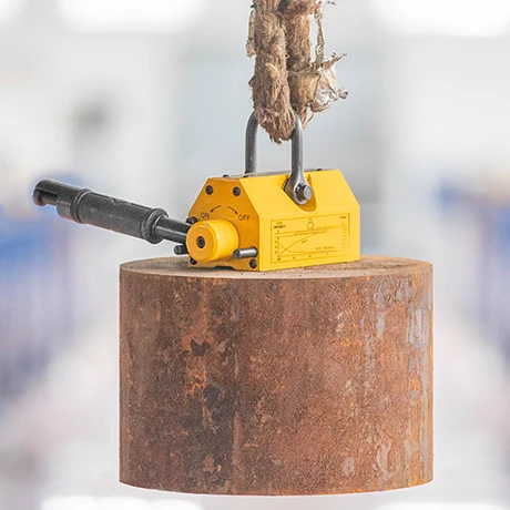
A permanent magnetic lifter picks up ferromagnetic loads without continuous electrical power. Its handle rotates or shifts an internal permanent-magnet rotor. In the ON position, magnetic flux is directed through the external pole shoes, across the workpiece and back into the lifter. In the OFF position, the flux is largely short-circuited inside the body, so little field reaches the load.
Core principle: the handle does not create or destroy magnetism. It changes the reluctance of two competing magnetic paths—one through the steel load and one inside the lifter.
Main Structure of a Manual Magnetic Lifter
| Component | Function | Important design point |
|---|---|---|
| Permanent-magnet rotor | Provides the magnetic source and switches orientation | Grade, magnet volume, temperature and pole direction |
| Fixed magnet or return circuit | Combines with or opposes the rotor field | Low leakage and repeatable switching torque |
| Low-carbon-steel yoke | Carries flux between the magnet and poles | Avoid local saturation and narrow bridges |
| Pole shoes | Transfer flux into the workpiece | Flatness, wear, pole spacing and contact area |
| Handle and shaft | Rotates the magnetic rotor | Mechanical advantage and positive end positions |
| Safety lock | Prevents accidental movement from ON to OFF | Must remain engaged under vibration and handling |
| Lifting eye and body | Transfers the mechanical load to the crane | Independent structural load path and proof testing |
How the ON and OFF Magnetic Circuits Work
In the ON position, the magnet polarities reinforce a circuit that exits one pole shoe, crosses a very small air gap into the steel load, travels through the load and returns through the other pole. A thick, low-carbon-steel workpiece offers low magnetic reluctance, allowing high flux and useful holding force.
In the OFF position, the rotating magnet redirects flux through internal steel bridges. The external poles see much less flux, allowing release. Residual attraction is never assumed to be exactly zero; it depends on steel hysteresis, clearances, surface condition and the internal magnetic circuit.
Some products use electro-permanent switching rather than a manual rotor. A short current pulse changes the state of one magnet set, while permanent magnets maintain holding force without continuous power. The electrical and safety architecture is different, but the same reluctance-path principle still applies.
Why Air Gap Reduces Lifting Force So Quickly
Air has far higher magnetic reluctance than steel. Rust, paint, scale, curvature, roughness, oil films and warped plates introduce an effective gap between the pole face and load. Even a small gap can reduce magnetic lifting force sharply. This is why catalog capacity is normally based on a clean, thick, flat, low-carbon-steel test plate—not an arbitrary factory component.
For an idealized pole, magnetic pressure is approximately proportional to B²/(2μ₀). Real lifters have leakage, uneven flux, saturation and edge effects, so this equation is useful for understanding trends, not for certifying a working load limit.
| Load condition | Effect on capacity | Required engineering check |
|---|---|---|
| Thin steel plate | Steel saturates and cannot carry all available flux | Use the manufacturer’s thickness derating curve |
| Paint, rust or mill scale | Creates a nonmagnetic air gap | Apply measured gap/surface derating |
| High-carbon or alloy steel | Permeability differs from reference steel | Test the actual alloy and heat treatment |
| Round bar or pipe | Small contact area and different flux path | Use V-poles and cylindrical-load rating |
| Hot workpiece | Magnet output and coercivity decrease | Confirm hot B-H curve and body temperature |
| Off-center lift | Introduces peel and tipping forces | Place the lifter over the center of gravity |
| Shock or acceleration | Dynamic force exceeds static weight | Control crane motion and apply the specified safety margin |
Magnet, Steel and Pole Design
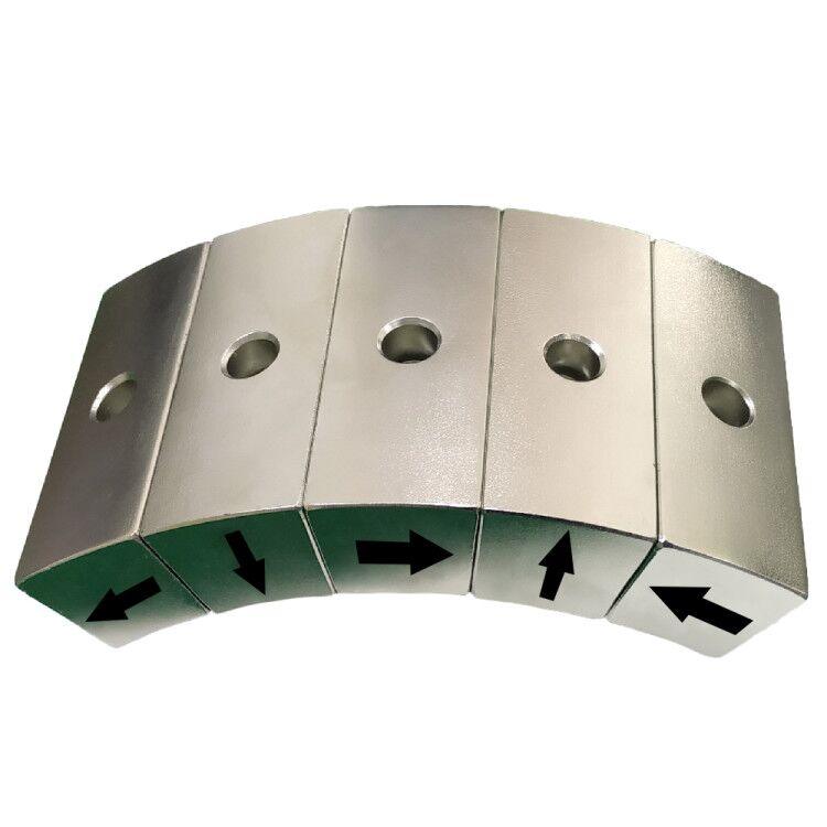
NdFeB provides high field in a compact rotor, while SmCo may be considered where temperature or corrosion stability dominates. The strongest custom neodymium magnets do not automatically produce the best lifter. If the steel yoke saturates, additional magnet volume adds leakage rather than useful pole flux. Pole width, spacing, yoke cross-section, rotor clearance and contact geometry must be solved together.
The mechanical system is equally important. The magnet must not serve as the structural fastener. The lifting eye, housing, shaft, bearings, stops and safety lock need a defined load path and fatigue margin. Switching torque must be manageable, yet the rotor must not move accidentally under vibration or a partial load.
Testing and Safe Use
A production test should include dimensional inspection, ON/OFF function, handle lock engagement, magnetic pull test on the specified reference plate, and verification at relevant gaps or plate thicknesses. Proof-load requirements and working-load labeling must follow the applicable local regulation and product standard. Published lifter manuals commonly warn that air gaps and thin plates reduce capacity; operators must use the exact model’s derating curves.
Before every lift, clean the pole face and load, inspect the lifter, confirm material and thickness, place the unit above the center of gravity, lock it fully ON and perform a low-height trial lift. Never pass a suspended load over people, exceed the rated capacity or assume a result from one steel grade applies to another.
Guande Design and Production Support
Guande develops the magnetic portion as a controlled magnetic assembly. We can review magnet grade and orientation, rotor and yoke geometry, pole saturation, machining tolerances, corrosion protection, switching fixtures and pull-force inspection. Related capabilities include custom NdFeB block magnets, disc magnets and custom magnetic assemblies.
For a new magnetic lifting device, send the target load, steel grade, minimum thickness, surface condition, temperature, contact geometry and required safety factor through our engineering inquiry form. We can then define the magnetic circuit and a measurable validation plan. Final certification of lifting equipment remains the responsibility of the qualified system manufacturer.