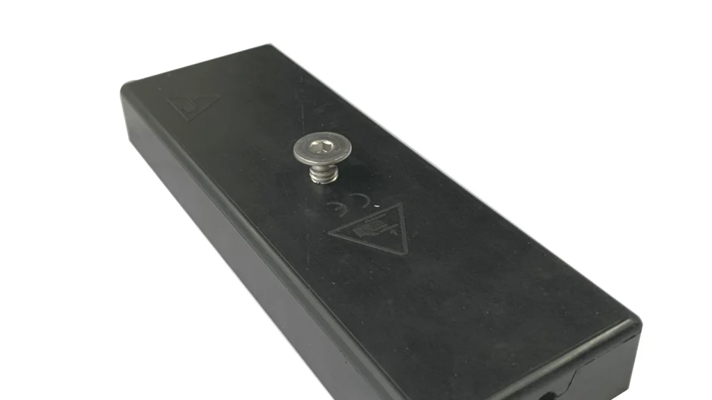
Rubber-coated magnets for wind turbine towers provide removable attachment points for light equipment on ferromagnetic tower surfaces. A rectangular assembly can offer a broad contact footprint, controlled orientation and one or more threaded interfaces without drilling the tower wall. Typical uses include temporary sensors, cable guides, inspection aids, labels and maintenance equipment.
Safety boundary: these magnets are not personnel anchors, certified lifting points or substitutes for engineered structural fasteners. Any item exposed to height, vibration or weather requires a risk assessment and an independent safety tether where falling objects are possible.
How the Rectangular Magnetic Circuit Works
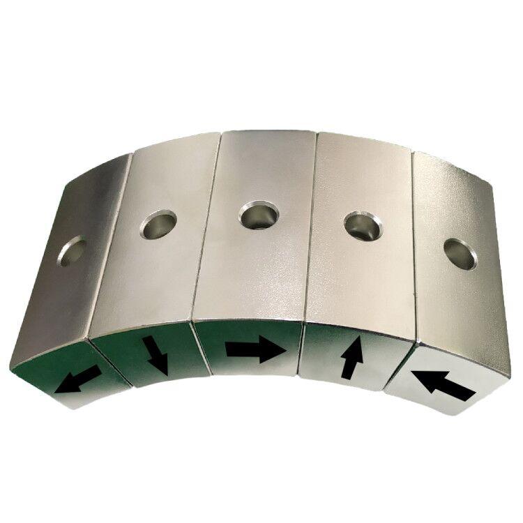
The assembly normally contains multiple NdFeB magnets bonded to a low-carbon-steel backing plate. The steel links the rear poles and directs useful flux toward the working face. Alternating magnet poles can create several short magnetic loops through the tower wall, while the rectangular footprint spreads contact pressure and resists rotation.
An elastomer layer—often TPE, TPU, EPDM or silicone—encapsulates or covers the magnetic circuit. It protects the tower coating and raises the friction coefficient. The rubber also creates an air gap, which reduces normal magnetic pull. The design therefore balances magnet volume, pole spacing, steel thickness and rubber thickness rather than maximizing any single item.
Why Rectangular Magnets Fit Tower Applications
| Design feature | Benefit on a steel tower | Trade-off |
|---|---|---|
| Long rectangular footprint | Controls rotation and supports elongated equipment | Must accommodate tower curvature |
| Rubber contact surface | Protects paint and increases sliding resistance | Reduces direct pull through the added gap |
| Multiple internal poles | Produces useful one-sided attraction | Needs uniform assembly orientation |
| Threaded insert or stud | Provides a repeatable equipment interface | Insert pull-out and corrosion must be validated |
| Encapsulated edges | Limits water and salt access to the magnet | Molding defects can compromise sealing |
Realistic Offshore Wind Tower Uses
| Application | Why magnetic mounting helps | Required check |
|---|---|---|
| Temporary vibration or temperature sensor | No drilling and fast relocation during diagnosis | Signal accuracy, tether and surface cleanliness |
| Cable or hose guide | Keeps temporary service lines organized | Shear load, abrasion and bend radius |
| Inspection camera or light | Quick positioning inside the tower | Secondary retention and vibration |
| Maintenance label or tool holder | Removable attachment without adhesive residue | Human-factor and falling-object control |
| Temporary protective cover | Holds a light barrier against steel | Wind pressure and edge peel |
| Commissioning instrumentation | Supports repeatable short-term measurement points | Calibration, cable force and removal plan |
Inside the tower, humidity, condensation and vibration usually dominate. External use adds UV, salt spray, rain, ice, large temperature swings and wind loading. The complete assembly must be specified for its actual zone rather than described simply as “marine grade.”
Tower Curvature and Surface Condition
A flat rectangular magnet touches a curved tower first along a limited line or at two edges. The remaining gap reduces magnetic force and may make the assembly rock under cable load. A compliant rubber face can absorb small deviations, but it cannot correct a large radius mismatch without adding too much magnetic gap. Long magnets should therefore be tested on a representative curved panel, or designed with segmented contact areas that follow the tower radius.
The tower’s protective paint system is also part of the magnetic circuit. Primer, intermediate coat and topcoat create a nonmagnetic gap, while texture and moisture change friction. The specification should use the maximum permitted coating build rather than a bare-steel laboratory plate. After removal, the contact area should be checked for gloss change, indentation and trapped contamination.
Pull Force Is Not the Same as Working Load
Published pull force is commonly measured perpendicular to a thick, clean, flat steel plate. A device mounted on a vertical tower is often loaded in shear. A first-order sliding estimate is:
Available shear resistance ≈ magnetic normal force × interface friction coefficient.
This is only a screening calculation. Tower paint thickness, curvature, surface water, oil, dust, rubber hardness and local deformation change both pull and friction. Cable tension can also create a peel moment that unloads one end of a rectangular magnet. Testing must reproduce the coated tower surface, curvature and load direction.
Marine Environment Design Controls
| Exposure | Failure mechanism | Design response |
|---|---|---|
| Salt and condensation | Corrosion through a damaged seal | Continuous encapsulation, compatible insert and leak inspection |
| UV and ozone | Elastomer cracking or hardening | Select an outdoor-rated compound and validate ageing |
| Temperature cycling | Differential expansion and bond stress | Control material compatibility and corner geometry |
| Vibration | Sliding, fretting or thread loosening | Use preload control, locking features and a tether |
| Tower coating | Indentation, staining or abrasion | Specify rubber hardness, texture and contact pressure |
| Galvanic contact | Local corrosion around hardware | Use compatible stainless inserts and isolation where required |
Rubber Thickness, Flatness and Molding Quality
A thinner working-face layer gives a stronger magnetic result but offers less tolerance to wear and molding variation. A thicker layer improves cushioning and sealing but increases the magnetic air gap. Even a small nonmagnetic gap can materially reduce attraction, especially for compact pole spacing.
Flatness matters because one raised corner can prevent full contact. Controlled insert location, balanced gates, venting and cooling reduce bubbles and warpage. Our guide to rubber-coated magnet mold design explains how material, magnetization sequence and molding parameters affect production.
Validation Before Installation
- Confirm that the attachment area is ferromagnetic and structurally suitable.
- Measure the real coating thickness, surface curvature and contamination.
- Test normal pull, shear, peel and rotation at minimum and maximum temperature.
- Condition samples for salt, humidity, UV and thermal cycling as applicable.
- Inspect rubber adhesion, sealing, insert torque and dimensional flatness.
- Define inspection intervals, removal limits and independent retention.
Guande Design and Production Support
Guande develops each custom magnetic assembly around the actual target surface and load. We can review NdFeB grade, pole arrangement, steel saturation, threaded hardware, rubber material, mold design, corrosion protection and force-test fixtures. Related material options are covered on our sintered NdFeB magnet page and in our rubber-coated magnet design guide.
Send the tower material, coating thickness, curvature, equipment mass, load direction, environment and required service life. We will evaluate the magnetic circuit and molding route using realistic test conditions.