A linear motor converts electrical energy directly into straight-line motion. It uses the same electromagnetic principles as a rotary motor, but the stator and rotor are conceptually unrolled into a track and a moving forcer. Because no ball screw, belt, rack, or gearbox is required, a linear motor can provide high acceleration, precise positioning, low mechanical backlash, and direct control of force.
Core principle: current in the coil interacts with the magnetic field across the air gap. Controlled three-phase current creates a traveling magnetic field, and synchronization between that field and the permanent-magnet track produces linear thrust.
Basic Linear Motor Structure
| Permanent-magnet track | Alternating N/S magnets on steel back iron create a periodic field |
|---|---|
| Working air gap | Mechanical clearance plus protective layers; strongly affects thrust |
| Coil forcer | Three-phase windings generate the traveling field |
| Linear guide | Carries payload and controls the air gap; the motor is not the bearing |
| Encoder | Provides position and velocity feedback for commutation and servo control |
| Cooling path | Removes copper and iron loss to protect continuous-force capability |
How Thrust Is Generated
In a permanent-magnet synchronous linear motor, the magnet track creates magnetic flux density B in the working gap. Current flowing through the active conductor length experiences electromagnetic force. A simplified conductor-level relationship is F = BIL, where I is current and L is active conductor length. A real three-phase motor includes winding distribution, pole pitch, harmonics, end effects, and control phase angle.
The servo drive commutates the phases according to mover position. The traveling field remains synchronized with the magnet poles and produces thrust in either direction. The motor force constant, often stated in newtons per ampere, links commanded current to force within the linear operating range.
Magnet-Track Design
Most compact linear motors use sintered NdFeB block magnets bonded to low-carbon-steel back iron with alternating polarity. The back iron closes the magnetic circuit and supports the magnets. Pole pitch is selected together with coil pitch and winding layout; changing it affects thrust density, force ripple, electrical frequency, and control behavior.
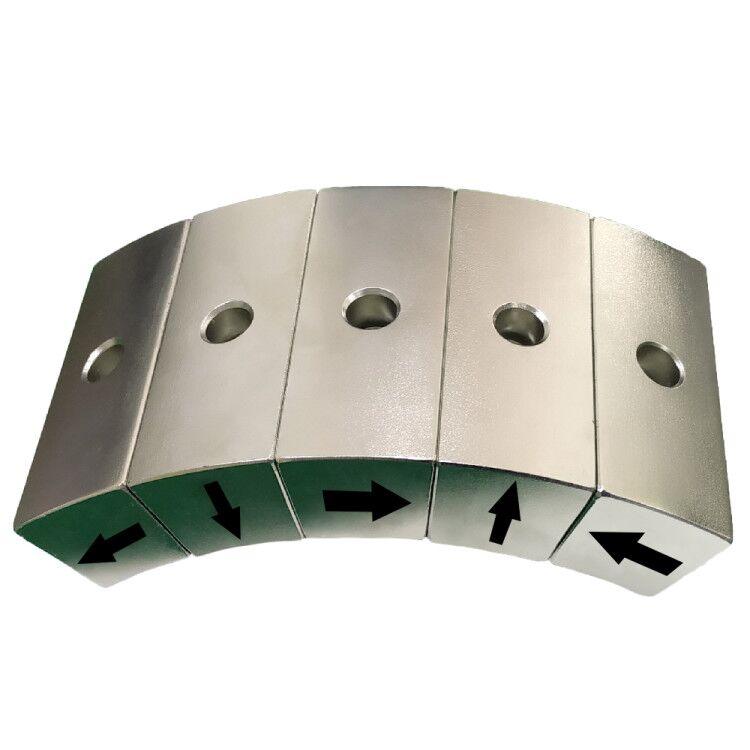
A Halbach magnet track can reinforce flux toward the coil while reducing leakage behind the array. It can reduce back-iron mass or improve working-gap field, but requires multiple magnetization directions and more demanding assembly. Our Halbach array capability supports these field-focused configurations.
Magnet-track diagram
| Steel back iron | Low-reluctance return path and structural support | ||||||
|---|---|---|---|---|---|---|---|
| Magnet poles | N | S | N | S | N | S | → travel direction |
| Air gap | Keep small and mechanically stable without contact | ||||||
| Three-phase coil | A | B | C | A | B | C | Traveling field |
Main Linear Motor Types
Iron-core flat linear motors
The windings are placed around laminated iron teeth. Iron increases flux linkage and thrust density, making this type suitable for high-force axes. The trade-offs are magnetic attraction between the forcer and track, cogging, force ripple, and added mover mass. Guides and machine structure must carry the normal attraction force.
Ironless U-channel linear motors
A lightweight resin-supported coil moves between two facing magnet tracks. With no iron teeth, cogging and magnetic attraction are very low. This supports smooth motion and high acceleration in precision stages. Continuous force per volume can be lower, and heat must leave the coil through a carefully designed thermal path.
Tubular linear motors
A cylindrical coil and magnet rod create force along a common axis. Tubular motors fit compact actuators, pick-and-place mechanisms, and reciprocating equipment. End effects, rod support, heat, and magnet retention require attention.
Voice-coil actuators
A voice coil is a short-stroke linear electromagnetic actuator. It provides force approximately proportional to current and is useful for focusing, vibration, precision force control, and fast small movements. Stroke and force are limited compared with long-track synchronous linear motors.
| Type | Main advantage | Main design issue | Typical use |
|---|---|---|---|
| Iron-core flat | High thrust density | Attraction, cogging, heat | Machine tools, transport axes |
| Ironless U-channel | Smooth motion, low moving mass | Cooling and magnet cost | Semiconductor and metrology stages |
| Tubular | Compact axial package | End effects and rod support | Packaging and reciprocating actuators |
| Voice coil | Fast force control | Short stroke | Optics, valves, vibration control |
Key Parameters Engineers Should Specify
- Continuous force: force available without exceeding the steady thermal limit.
- Peak force and duration: acceleration or disturbance force allowed for a defined time.
- Force constant: newtons per ampere under stated temperature and air-gap conditions.
- Back-EMF constant: generated voltage per velocity; affects drive-voltage margin.
- Pole pitch: sets the relationship between magnet pattern, winding, and electrical frequency.
- Air gap: includes clearance, coating, cover, flatness, and guide tolerance.
- Cogging and force ripple: important for low-speed precision and surface finish.
- Thermal resistance: links copper loss to winding and magnet temperature.
- Encoder resolution and latency: determines commutation quality and servo performance.
Magnet Grade and Temperature
The highest room-temperature NdFeB grade is not automatically the best motor magnet. Coil current produces a reverse field, and magnet temperature may be much higher than ambient. Grade selection must provide intrinsic-coercivity margin at the worst current, air gap, and temperature.
High-coercivity H, SH, UH, or higher-temperature families may be appropriate. The exact suffix does not guarantee a universal temperature because the safe operating point depends on magnet geometry and the circuit. Coatings and adhesive must also match humidity, coolant, cleaning agents, and thermal cycling.
Guande supplies custom NdFeB block magnets with controlled magnetization direction, geometry, coating, and magnetic inspection for linear tracks.
Force Ripple, Cogging, and End Effects
Cogging comes from interaction between permanent magnets and iron teeth even when no current flows. Force ripple also comes from winding harmonics, pole-position errors, magnet variation, and commutation error. Skew, optimized magnet width, fractional slot arrangements, pole shaping, and current compensation can reduce these effects.
At the ends of a finite magnet track, the field is not periodic. Entry and exit forces, back-EMF variation, and available thrust can change. The design should include sufficient overtravel or end compensation rather than assuming an infinite repeating model.
Common Applications
- Semiconductor lithography, wafer handling, and inspection stages.
- CNC machines, laser cutting, grinding, and precision machining axes.
- Packaging, printing, electronics assembly, and pick-and-place systems.
- Industrial robots, gantries, and high-speed material handling.
- Metrology, optical alignment, microscopy, and laboratory automation.
- Medical imaging tables, pumps, and controlled-motion equipment.
- Transport, sorting, and long-travel automated production lines.
Practical Validation
A useful prototype plan measures no-load cogging, force constant, back-EMF, continuous temperature rise, peak-force duration, encoder commutation, force ripple, and hot demagnetization margin. Magnet-track flatness, pole sequence, adhesive bondline, magnetic moment, and coating must be inspected before system testing.
Guande supports magnetic-circuit review, magnet geometry, alternating-pole and Halbach assembly, steel back iron, bonding fixtures, and field mapping. For a completed track or integrated mover, our custom magnetic assembly process aligns the magnetic specification with measurable production controls.
Frequently Asked Questions
Is a linear motor more accurate than a ball screw?
It removes backlash and transmission compliance, but final accuracy still depends on encoder quality, guides, thermal stability, structure, servo tuning, and disturbance forces.
Why do linear motors need cooling?
Continuous force requires current, and copper loss rises with current squared. Without an effective cooling path, winding temperature limits continuous thrust and can heat nearby magnets and machine structures.
Can a Halbach array improve a linear motor?
It can concentrate flux toward the coil and reduce back-side leakage. The benefit must be compared with added magnetization, assembly, and tolerance complexity.
Send Guande your force-speed profile, stroke, air gap, pole pitch, temperature, and track envelope for a concise linear-motor magnet review.