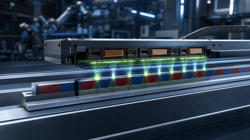
A linear motor converts electrical energy directly into straight-line motion. It can be understood as a rotary motor opened along its circumference and laid flat: the stator becomes a magnet track or energized primary, while the rotor becomes a moving forcer. Because no ball screw, belt or rack is required between the motor and the load, the system can achieve high acceleration, accurate positioning and low mechanical backlash.
Core idea: a controlled traveling magnetic field interacts with the permanent-magnet field in the air gap. Their electromagnetic force acts along the rail and produces thrust.
The Working Principle
In a permanent-magnet synchronous linear motor, alternating north and south poles are fixed along a track. A three-phase winding in the forcer receives sinusoidal or commutated current. The drive changes current phase according to the encoder position, creating a traveling field that remains synchronized with the magnet poles. The interaction generates continuous linear thrust.
At conductor level, the force direction follows the Lorentz relationship F = BIL, where B is flux density, I is current and L is the active conductor length. A complete motor has many conductors and a three-dimensional magnetic circuit, so designers normally use a force constant in N/A and finite-element analysis rather than this simplified equation alone.
Main Components
| Component | Function | Design concern |
|---|---|---|
| Magnet track | Creates alternating air-gap flux | Pole pitch, grade, magnetization, adhesive and steel back iron |
| Coil forcer | Creates the traveling electromagnetic field | Copper fill, insulation, cooling and current density |
| Back iron or U-channel | Completes and concentrates the magnetic circuit | Saturation, attraction force, mass and eddy-current loss |
| Encoder | Reports position for commutation and servo control | Resolution, latency, alignment and contamination |
| Linear guide | Controls straightness and air gap | Stiffness, preload, lubrication and thermal growth |
Iron-Core, Ironless and Tubular Designs
| Architecture | Strength | Trade-off | Typical use |
|---|---|---|---|
| Iron-core flat motor | High continuous and peak force per package | Magnetic attraction and cogging must be managed | Machine tools, presses, packaging and transport |
| Ironless U-channel | Very low cogging and smooth force | Lower force density and more magnet material | Semiconductor, metrology, optics and scanning |
| Slotless iron-core | Balance of force density and low ripple | More complex thermal and magnetic design | Precision automation |
| Tubular linear motor | Compact coaxial force and enclosed geometry | Stroke, cooling and cable routing constraints | Actuators, dosing, handling and robotics |
Why NdFeB Is Commonly Used
A compact neodymium magnet motor track can provide high remanence and energy product, allowing strong air-gap flux without continuous field-coil power. The selected neodymium magnet for motor duty must also have adequate intrinsic coercivity at the worst track temperature. Higher Br is useful only when the back iron remains below saturation and the air gap, pole pitch and winding are correctly matched.
Magnet segments are usually assembled with alternating polarity. Skewed edges, fractional pole arrangements or optimized pole arcs can reduce force ripple. A Halbach array rotates the magnetization direction across successive blocks to reinforce flux on the coil side and reduce stray flux on the back side. It can improve force density or reduce back-iron mass, but it increases assembly complexity and demands accurate orientation.
Parameters That Control Real Performance
| Parameter | Why it matters | Common design action |
|---|---|---|
| Continuous force | Limited mainly by allowable coil temperature | Size cooling and copper for the duty cycle |
| Peak force | Sets acceleration and disturbance rejection | Check current limit, saturation and duration |
| Force constant, N/A | Links current to thrust | Validate at the production air gap |
| Cogging / force ripple | Affects velocity stability and surface finish | Optimize slots, pole pitch, skew and commutation |
| Air gap | Strongly influences flux and tolerance sensitivity | Include guide error, adhesive and protective cover |
| Back-EMF constant | Sets drive voltage at speed | Check maximum velocity and DC bus margin |
Where Linear Motors Are Used
- Semiconductor and electronics: wafer stages, inspection, dispensing and pick-and-place.
- Machine tools: high-speed axes, laser cutting and precision grinding.
- Packaging: independently controlled movers, indexing and synchronized product handling.
- Robotics: gantries, transfer axes and direct-drive end-effector positioning.
- Medical and laboratory equipment: imaging tables, sample handling and quiet precision motion.
- Transport and logistics: shuttles, sorting, doors and long-stroke automation.
Design Errors to Avoid
Do not size the magnet track from catalog surface gauss alone. Useful thrust depends on air-gap flux distribution, winding geometry and phase current. The steel return path can saturate, while an overly large air gap wastes magnet volume. Thermal expansion may change the gap or encoder scale. Conductive covers and back plates can also create eddy-current heating at high speed.
Mechanical assembly deserves equal attention. Alternating magnets generate strong attraction and repulsion before bonding. A controlled fixture, polarity verification, adhesive thickness, cure process and retention feature are needed. Long tracks should be divided into serviceable modules with repeatable pole pitch.
Controls, Cooling and Position Feedback
A direct-drive axis is a system, not only a magnet track. The servo drive must know the electrical phase position before it can command efficient thrust. Absolute or incremental encoders, Hall sensors and a controlled homing sequence are common solutions. Current-loop tuning affects force response, while position-loop tuning depends on guide stiffness and load resonance. Cooling may use natural convection, an aluminum cold plate or liquid channels. Continuous-force claims are meaningful only when the same winding temperature limit and cooling condition are used. Cable-chain drag, encoder thermal drift and moving-cable fatigue should be included in the acceptance test.
How Guande Supports Linear-Motor Projects
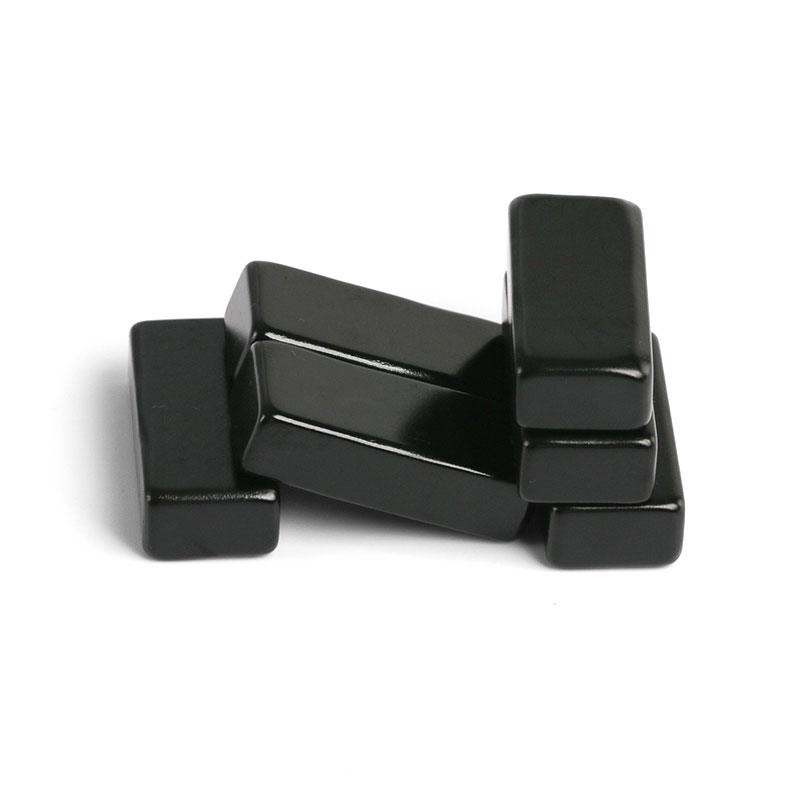
We support prototype and production magnet tracks using precision NdFeB block magnets, segmented pole sets and custom Halbach arrays. Our process covers grade review, magnetization direction, dimensional inspection, assembly fixtures, polarity mapping and flux consistency. Where the magnetic circuit is integrated with steel or aluminum, our custom magnetic assembly team can review retention and manufacturability.
For a useful technical review, provide pole pitch, target force, stroke, air gap, maximum speed, current limit, cooling method and operating temperature through the Get a Quote page. We will respond with practical material and assembly options rather than a generic grade recommendation.