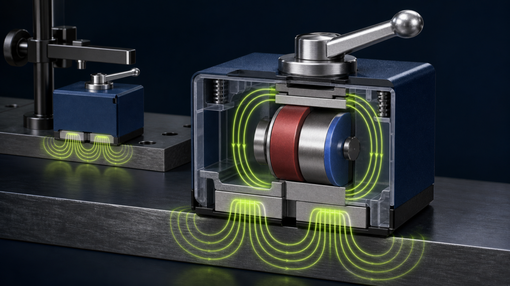
A switchable permanent magnet provides strong temporary holding without consuming electrical power continuously. The magnet material itself is not turned off. A mechanical lever or an electrical pulse changes the magnetic circuit so that most flux either crosses the external steel workpiece in the ON state or closes inside the device in the OFF state.
Important distinction: this article covers ON/OFF permanent-magnet bases, holders and clamps. Reed switches and Hall-effect sensors are electrical switching components and use a different design principle.
The Magnetic-Circuit Principle
Magnetic flux follows the path with the lowest reluctance. A switchable device combines one or more permanent magnets with low-carbon-steel pole pieces, a housing, nonmagnetic separators and a controlled moving element. In the ON position, the poles are arranged so flux leaves one pole face, crosses the ferromagnetic workpiece and returns through the opposite pole. The workpiece completes the circuit and creates holding force.
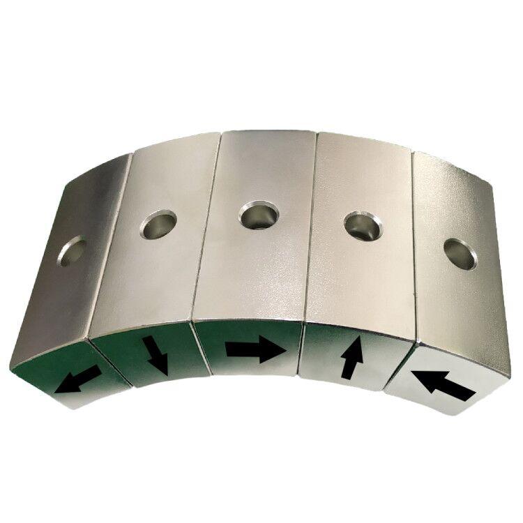
In the OFF position, a rotating or sliding magnet redirects flux through an internal steel path. Two magnets may also be aligned so their external fields reinforce in ON and oppose in OFF. The residual field is reduced, not mathematically zero. Thin sheet, stainless steel, paint, rust and surface curvature can prevent an otherwise correct magnetic base assembly from reaching its rated force.
Main Structure
| Part | Function | Design requirement |
|---|---|---|
| Permanent magnet | Supplies the magnetic potential | Correct grade, geometry, temperature margin and magnetization |
| Steel pole pieces / yoke | Guides flux to the contact faces | Low reluctance without local saturation |
| Nonmagnetic spacer | Separates north and south poles | Controls leakage and protects the flux path |
| Rotor, slider or shunt | Changes the internal magnetic circuit | Repeatable angular position and low wear |
| Lever and stops | Provides user control | Safe torque, positive detent and overload resistance |
| Contact poles | Transfer flux into the workpiece | Flatness, wear resistance and clean contact |
Common ON/OFF Architectures
| Architecture | How switching occurs | Strength | Constraint |
|---|---|---|---|
| Rotating cylindrical magnet | A quarter-turn connects external or internal pole paths | Compact and mechanically simple | Rotor torque rises with magnet size |
| Dual permanent magnets | One magnet rotates between reinforcing and opposing alignment | Good ON/OFF contrast | Needs accurate magnet matching and stops |
| Moving flux shunt | A steel shunt bypasses or exposes the workpiece path | Adaptable to unusual geometries | Sliding surfaces can wear or collect debris |
| Electro-permanent magnet | A short current pulse reverses one magnetic element | Remote switching with near-zero holding power | Requires coil, controls and functional-safety analysis |
What Determines Holding Force?
The rated pull force is normally measured in direct tension on a clean, flat and sufficiently thick low-carbon-steel plate. Real installations often provide less force. A small air gap has a large effect because air has much higher reluctance than steel. Paint, plating buildup, surface roughness, weld scale or a label all act as gaps.
Workpiece thickness also matters. If the plate is too thin, it saturates and cannot carry all available flux. Curved contact reduces effective pole area. In shear, the load is limited mainly by friction, so a 1,000 N pull rating does not equal 1,000 N of safe sideways capacity. Dynamic shock, vibration and leverage require an application-specific safety factor.
| Condition | Effect on holding | Recommended check |
|---|---|---|
| Paint, adhesive film or rust | Creates an air gap and lowers flux | Test at the maximum real coating thickness |
| Thin or low-permeability target | Limits the return path | Measure pull on the actual alloy and thickness |
| Curved or uneven surface | Reduces contact area | Use contoured poles or a dedicated fixture |
| High temperature | Reduces magnet output and can cause irreversible loss | Review hot B-H curves and nearby heat sources |
| Shear or impact load | Depends on friction and load direction | Add stops, pins or secondary retention |
Typical Applications
- Metrology: dial-indicator bases, sensor arms and temporary alignment tools.
- Welding and fabrication: positioning stops, grounding attachments and workpiece location.
- Machining: temporary fixtures, tool-setting supports and inspection devices.
- Automation: robot end-of-arm gripping, changeable guides and pallet location.
- Material handling: sheet separation, transfer and qualified lifting devices.
- Optics and laboratories: repositionable mounts on ferromagnetic tables.
A general-purpose switchable magnet should not be used as a personnel-support or lifting device unless the complete assembly is designed, tested and certified for that duty. Switching under load can cause sudden movement. Residual attraction in OFF must also be considered around chips, medical devices and magnetically sensitive equipment.
Design and Validation Checklist
- Define the target material, thickness, curvature and surface coating.
- State load direction, working load, shock, vibration and required safety factor.
- Set the maximum switch torque and available lever movement.
- Check pole saturation and leakage using magnetic-circuit analysis or FEA.
- Measure ON pull force, OFF residual force and switch torque on production parts.
- Run cycle-life, contamination, corrosion and temperature tests.
- Add mechanical retention when a magnetic release could create a hazard.
Residual Force and Service Behavior
The OFF state should be specified as a measurable residual pull force at a defined gap, not described as “zero magnetism.” Steel chips can bridge the pole faces and make release inconsistent. Periodic cleaning, pole-face inspection and confirmation of lever travel are therefore part of normal service. For automated equipment, a position sensor can verify the switching state, while a mechanical stop or secondary gripper should carry any load whose unexpected release could damage equipment.
How Guande Develops Switchable Magnetic Assemblies
A reliable magnetic switch assembly depends on the complete magnetic and mechanical stack. We can review NdFeB or SmCo grade, pole geometry, steel material, clearances, nonmagnetic spacers, coatings and assembly fixtures. Prototype inspection can include pull-force curves, switch torque, residual field, polarity mapping, dimensional checks and repeated switching.
Projects may use precision disc magnets, block magnets and machined steel components. For integrated fixtures or robot tooling, our custom magnetic assembly service covers design-for-manufacture, bonding, controlled magnet insertion and production inspection.
Send the target steel specification, contact envelope, working load, load direction, temperature and switching method through Get a Quote. We will convert the requirement into a testable assembly specification.