A permanent magnet synchronous motor (PMSM) uses permanent magnets on or inside the rotor to establish the main rotor field. Three-phase stator currents create a rotating magnetic field. Electromagnetic torque pulls the rotor field into alignment with the stator field, so the rotor turns at synchronous speed without the steady-state slip required by an induction motor.
Core point: NdFeB magnets provide rotor flux; they do not regulate the motor by themselves. Torque, speed, efficiency and demagnetization margin depend on the stator, inverter control, rotor topology, cooling and the complete magnetic circuit.
The PMSM Working Principle
The inverter converts DC-link power into controlled three-phase stator currents. The windings produce a rotating field whose electrical frequency determines synchronous speed:
Synchronous speed ns = 120f / P
Here, f is electrical frequency in hertz and P is the total number of magnetic poles. For example, a four-pole motor supplied at 100 Hz has a synchronous speed of 3,000 rpm. The controller changes frequency to command speed and regulates current to produce torque.
In field-oriented control, stator current is resolved into a flux-axis component and a torque-axis component. Surface-magnet machines obtain most torque from interaction between stator current and permanent-magnet flux. Interior permanent magnet (IPM) machines can also produce reluctance torque because the rotor has different magnetic reluctance along its d and q axes.
What NdFeB Magnets Do in the Rotor
| Magnet function | System effect | Design variable |
|---|---|---|
| Create rotor excitation | Eliminates rotor excitation windings in the main field path | Magnet volume, Br and pole coverage |
| Set air-gap flux | Influences torque constant and back EMF | Air gap, steel saturation and magnet thickness |
| Support compact torque density | Allows high flux from a relatively small rotor | Grade, topology and cooling |
| Follow the rotating stator field | Maintains synchronous operation | Pole count and control angle |
| Enable generator operation | Produces back EMF when mechanically driven | Speed, winding turns and flux linkage |
NdFeB is widely used because it combines high remanence and energy product with useful coercivity. This allows compact motors for traction, servos, robotics, pumps and compressors. SmCo may be evaluated when very high temperature or corrosion stability outweighs cost and lower room-temperature energy density.
Common Rotor Topologies
| Topology | Magnet arrangement | Engineering characteristics |
|---|---|---|
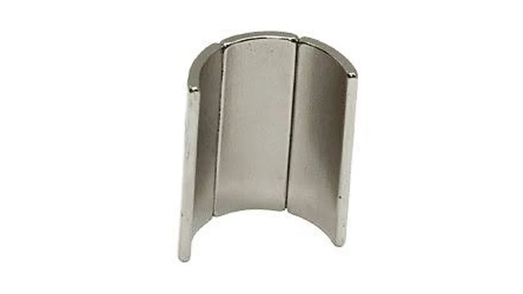
| Surface PMSM | Arc or block magnets bonded to the rotor surface | Simple flux path; retention and high-speed stress require care |
| Interior PMSM | Blocks or shaped segments buried in rotor slots | Mechanical containment and reluctance torque; complex bridges |
| Spoke rotor | Magnets oriented radially between steel poles | Flux concentration with leakage and assembly challenges |
| Axial-flux PMSM | Sector or trapezoidal magnets on a rotor disc | Short axial package and high diameter-to-length ratio |
| Outer-rotor PMSM | Magnets mounted inside an external rotating shell | High torque leverage and application-specific retention |
Why Magnet Grade Selection Is an Operating-Point Decision
A high room-temperature grade is not automatically safer. Remanence controls available flux, while intrinsic coercivity Hcj controls resistance to irreversible demagnetization. NdFeB flux output normally decreases as temperature rises, and reverse d-axis current during field weakening can oppose the magnet field.
| Input | Why it matters | Required review |
|---|---|---|
| Maximum magnet temperature | Reduces Br and coercivity | Thermal model and hot demagnetization curve |
| Peak reverse current | Moves the magnet operating point toward the knee | Worst-case inverter and fault condition |
| Rotor bridge and air gap | Change permeance, leakage and saturation | FEA at tolerance extremes |
| Magnet edge geometry | Can create local demagnetization zones | Segment-level field analysis |
| Coating and adhesive | Affect corrosion, bond reliability and thermal path | Environmental and process validation |
For a reliable design, the local magnet operating point should stay away from the irreversible knee across hot running, field weakening, short-circuit and manufacturing tolerance conditions. Higher-Hcj grades, grain-boundary diffusion, magnet thickness changes or rotor redesign may provide margin.
Torque, Back EMF and Field Weakening
More rotor flux can increase low-speed torque per ampere, but it also raises back EMF. Above base speed, the inverter may apply negative d-axis current to weaken the effective air-gap field and stay within the DC-link voltage limit. That opposing field increases demagnetization stress and copper loss. The best magnet specification therefore balances torque, voltage, speed range and thermal margin.
IPM motors use saliency to generate reluctance torque, reducing the amount of magnet torque required at some operating points. Rotor bridges must contain centrifugal force, yet excessive bridge thickness can shunt flux. This mechanical–magnetic trade-off is one reason rotor design cannot be separated from magnet selection.
Losses and Magnet Segmentation
Although the magnets create a static rotor field in the rotor reference frame, slot harmonics and inverter harmonics can induce eddy currents in conductive NdFeB. Large continuous magnets may heat more than segmented magnets. Axial or circumferential segmentation interrupts current paths, but adds adhesive gaps, assembly steps and magnetic tolerances.
Motor efficiency still includes stator copper loss, core loss, windage, bearing loss and inverter loss. Permanent magnets reduce rotor excitation loss; they do not eliminate the rest. Our earlier guide explains the broader advantages and design limits of PMSMs.
Applications and Magnet Priorities
| Application | Main priority | Magnet design focus |
|---|---|---|
| EV traction | Wide speed range and high torque density | Hot Hcj, field weakening and retention |
| Industrial servo | Low ripple and rapid response | Pole consistency, skew and magnetic mapping |
| HVAC compressor | Efficiency and reliability | Temperature, corrosion and balance |
| Robot joint | Compact size and controllability | Low cogging and assembly accuracy |
| Direct-drive generator | High torque at low speed | Large pole count, segmentation and service environment |
Guande Motor Magnet and Rotor Support
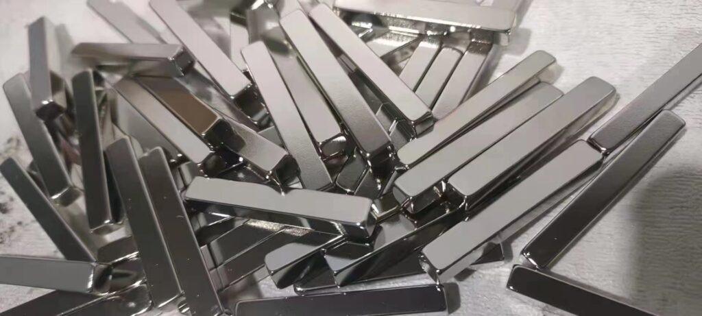
Guande supplies precision NdFeB arc magnets, blocks and application-specific segments for surface, interior and axial-flux motors. Our rotor magnet assemblies can include pole sorting, fixture-controlled bonding, steel hubs, sleeves, dimensional inspection, magnetic mapping, runout and balance control. We also support broader custom magnetic assemblies.
Send the motor topology, pole count, air gap, speed range, current limit, magnet temperature and target back EMF. We will review the magnet grade, geometry, orientation and inspection plan against the real operating point.