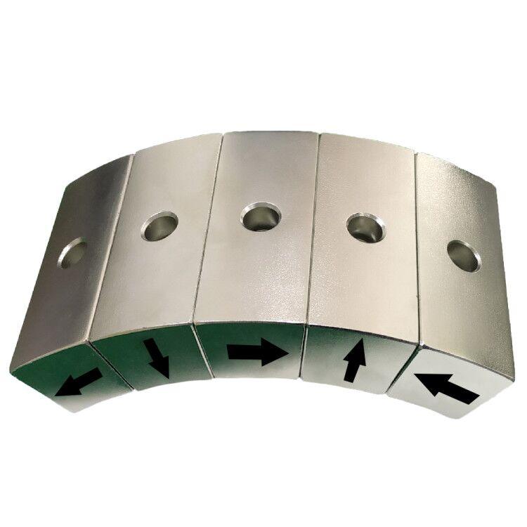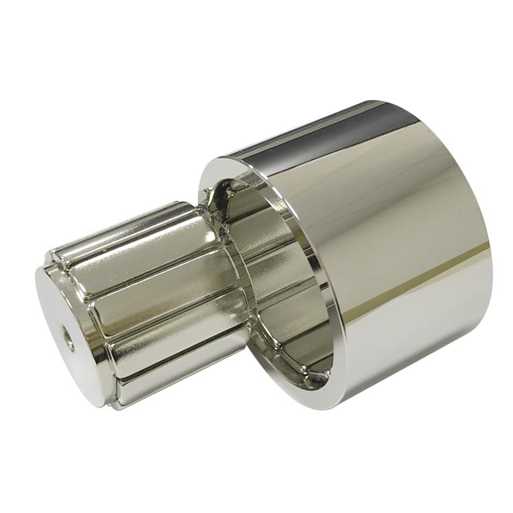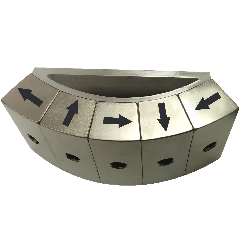
Industrial robotic arms need high torque density, smooth motion, compact joints, accurate sensing, and controlled stray fields. Halbach magnet arrays can help achieve these goals by arranging permanent magnets with rotating magnetization directions so that the field is reinforced on one side of the array and reduced on the other.
Important distinction: not every industrial robot uses a Halbach array. The configuration is most valuable when a concentrated working field, low leakage, light moving mass, or smooth direct-drive motion justifies the added magnetization and assembly complexity.
Why Halbach Arrays Suit Robotic Systems
A conventional north-south magnet arrangement sends useful flux into the working gap but also allows more leakage behind the magnets. A Halbach sequence rotates the magnetization vector from segment to segment. In an ideal arrangement, this strengthens flux toward the motor air gap, linear coil, workpiece, or sensor while weakening the field on the opposite side.
For a robot designer, the potential benefits include more torque or force from a given magnet volume, reduced back iron, lower rotor inertia, less magnetic interference with nearby encoders, and a compact actuator envelope. Actual improvement depends on pole pitch, segment count, working gap, steel saturation, temperature, and manufacturing tolerance.
1. Cylindrical Halbach Rotors for Robot Joints
Cylindrical or multipole Halbach rings are used in frameless torque motors, direct-drive joints, and compact servo actuators. Magnet segments are arranged around a rotor so the strong field faces the stator air gap. The field on the rotor’s inner side can be lower, which may reduce the need for heavy back iron and help lower inertia.
This arrangement is attractive in shoulder, elbow, and wrist joints where torque-to-weight ratio affects payload and acceleration. A larger number of magnet segments can approximate a smoother rotating magnetization, but it also increases assembly cost and orientation-control requirements. See our rotor magnet solutions for custom magnetized and assembled motor rotors.
2. Axial-Flux Halbach Rings and Discs
Axial-flux Halbach arrays direct a reinforced field toward a flat stator across an axial air gap. Their disc-like geometry can suit thin wrist joints, end-of-arm rotary modules, and compact actuators where axial length is limited.
These arrays must be designed together with the bearing system because axial magnetic attraction can be significant. Disc flatness, axial runout, magnet retention, and air-gap control directly affect torque ripple and efficiency.
3. Linear and Planar Halbach Arrays
Linear Halbach arrays place rectangular or shaped magnets in a repeating sequence along a track. The concentrated field faces the coil or reaction plate. They can be used in robotic linear axes, precision stages, pick-and-place systems, and direct-drive gantries where low friction and fast response are valuable.
Planar versions may also support magnetic grippers or end effectors by strengthening the field toward a steel workpiece while reducing leakage toward the robot body. The working gap is critical: magnetic force falls quickly as distance increases, so protective covers, paint, surface curvature, and part variation must be included in the design.
4. Halbach Cylinders for Sensors and Special End Effectors
A Halbach cylinder can produce a relatively strong, uniform field inside its bore while limiting the external field. In robotic systems, this principle can support calibration fixtures, magnetic sensing modules, sample handling, or specialized inspection and medical automation.
The required field uniformity determines magnet count, magnetization angles, bore size, length, and end compensation. A simple eight-segment cylinder may be sufficient for one application, while precision instrumentation may need more segments and detailed field mapping.
5. Halbach Arrays for Magnetic Damping and Braking
Some robotic axes, test rigs, and safety mechanisms use Halbach arrays with conductive plates to generate eddy-current damping or noncontact braking. Relative motion induces currents in the conductor, and their magnetic field opposes the motion. The result is smooth, wear-free damping without friction contact.
This function produces heat and its force depends on speed, conductivity, gap, and magnet pattern. It is normally a supplemental damping or braking method rather than a complete holding brake for a stationary loaded robot joint.
Which Magnet Material Is Used?
Sintered NdFeB is common when the priority is maximum field and torque from minimum mass. High-coercivity grades may be needed because robot motors can experience winding-generated reverse fields and elevated temperatures. SmCo can be considered for higher temperatures, improved corrosion resistance, or greater magnetic stability, although it is typically more expensive and mechanically brittle.
Material selection should use the actual operating point. A stronger room-temperature grade is not automatically safer if coercivity margin becomes inadequate at maximum winding temperature.
How Engineers Select the Halbach Configuration
| Robotic function | Typical Halbach form | Main design priority |
|---|---|---|
| Shoulder or elbow joint motor | Cylindrical multipole rotor | Torque density and low inertia |
| Thin wrist rotary module | Axial-flux ring or disc | Short axial package and smooth torque |
| Linear axis or precision stage | Linear or planar array | High force, low ripple, and controlled leakage |
| Magnetic gripper | Planar one-sided array | Working-side force and reduced back-side field |
| Sensor or calibration module | Halbach cylinder | Uniform bore field and low external leakage |
| Noncontact damper | Linear or arc array near conductor | Predictable speed-dependent braking force |
Critical Design Inputs
- Required torque, force, field strength, and allowable ripple.
- Available diameter, length, mass, and rotor-inertia target.
- Working gap, cover thickness, and tolerance stack.
- Pole count, pole pitch, magnet thickness, and magnetization vectors.
- Maximum coil and magnet temperature plus demagnetizing field.
- Speed, centrifugal load, vibration, shock, and service life.
- Encoder location and acceptable stray-field level.
- Carrier, sleeve, adhesive, corrosion protection, and repair strategy.
Manufacturing and Assembly Challenges
Halbach assembly is more demanding than placing identical radial magnets around a rotor. Neighboring segments can attract, repel, rotate, or eject themselves from a fixture because their magnetization directions differ. Angular placement error and magnetization-direction error change the final field distribution and can increase torque ripple.
Safe production requires orientation identification, robust fixtures, controlled adhesive gaps, reliable mechanical retention, and a defined assembly sequence. High-speed rotors may need a nonmagnetic retaining sleeve, runout control, and dynamic balancing. For full-array solutions, visit our Halbach array capabilities.
Inspection for Robotic Halbach Assemblies
Individual magnets can be checked for dimensions, magnetization direction, flux, coating, and appearance. The completed array should then be evaluated as a system. Depending on the application, inspection may include surface-field mapping, air-gap flux measurement, harmonic analysis, back-EMF testing, torque or force testing, runout, balance, thermal cycling, vibration, and overspeed validation.
Guande supports magnetic-circuit review, custom magnet geometry, multipole and vector magnetization planning, assembly tooling, adhesive and sleeve integration, and application-level inspection. Our custom magnetic assembly service helps bridge the gap between a simulated Halbach pattern and a repeatable production component.
Frequently Asked Questions
Do Halbach arrays always produce more robot motor torque?
No. They can concentrate useful flux and reduce leakage, but the result depends on the complete motor geometry, air gap, stator, steel saturation, winding, pole count, and thermal limits. Simulation and prototype testing are still required.
Are Halbach magnets one specially magnetized ring?
They can be made from individually magnetized segments, a multipole magnetized ring, or a hybrid construction. Segmented arrays offer design flexibility; one-piece rings can simplify assembly but impose different size and magnetization limits.
Can a Halbach array be used in a robotic gripper?
Yes. A planar one-sided array can direct more field toward the workpiece and reduce the back-side field. Holding force still depends strongly on the air gap, steel thickness, contact area, surface condition, and safety factor.
Send Guande your robotic axis geometry, field or torque target, speed, temperature, and working gap for a Halbach array feasibility review.