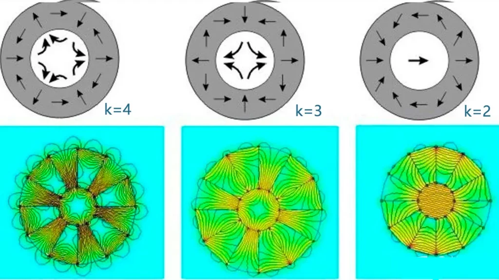
A Halbach array arranges permanent-magnet segments so the magnetization direction rotates from one segment to the next. The fields reinforce on the working side and partially cancel on the opposite side. In a cylinder, the same principle can concentrate flux inside the bore or outside the ring. This field shaping is useful when more working-gap flux, lower leakage or reduced back iron justifies a more complex assembly.
Design point: “Halbach” describes a magnetization pattern, not one fixed product. Segment count, pole order, air gap, magnet grade and mechanical retention determine whether the real assembly produces a useful advantage.
Common Halbach Geometries
| Geometry | Field objective | Typical use |
|---|---|---|
| Linear array | Strong field on one face, weak field on the back | Linear motors, magnetic tracks, inspection and holding |
| External-field cylinder | Concentrate flux outside the ring | Rotary motor rotors and magnetic wheels |
| Internal-field cylinder | Create a strong multipole field in the bore | Couplings, beam devices, sensors and compact field sources |
| Planar two-dimensional array | Shape flux over an area | Levitation, stages and specialized fixtures |
| Paired arrays | Create a controlled field in the gap | Linear actuators and test equipment |
1. Rotary and Linear Motors
In a Halbach array motor, the magnetization sequence directs more flux toward the stator. This can improve torque density or reduce the required rotor back iron. Linear Halbach arrays are used where a moving coil or forcer needs strong, periodic gap flux with low cogging. Precision positioning equipment can benefit from the clean field distribution, but only when segment orientation and pitch errors are tightly controlled.
The array does not eliminate losses. Magnet segmentation, electrical conductivity and spatial harmonics still influence eddy-current heating. At high speed, the retention sleeve, adhesive and balance quality can dominate feasibility. Compare these requirements with conventional rotor magnet assemblies before selecting the topology.
2. Magnetic Wheels and Non-Contact Drives
A cylindrical array can form repeated external poles for a magnetic wheel or magnetic gear-like mechanism. Concentrating flux toward the target surface can increase usable tangential force without increasing magnet volume. These systems appear in wall-climbing robots, sealed transmissions and synchronized conveyors.
Performance remains highly sensitive to stand-off distance. Steel thickness, surface curvature and air gap should be included in the model. See our engineering comparison of direct-contact and non-contact magnetic wheel design.
3. Magnetic Couplings and Sealed Equipment
An internal-field or external-field Halbach cylinder can transmit torque through a nonmagnetic containment wall. Field concentration can reduce leakage outside the coupling and improve torque per magnet volume. Pumps, mixers, vacuum equipment and isolated mechanisms may benefit when shaft seals are undesirable. The containment can, conductivity and temperature still limit speed and torque; metallic cans can create eddy-current heat.
4. Sensors, Encoders and Calibration Fields
A multipole ring can provide a repeatable sinusoidal field for magnetic encoders or angle sensors. An internal-field cylinder may create a relatively strong field inside a compact bore for calibration and research. Sensor accuracy depends on magnetization-angle error, segment position, temperature coefficient and runout. A good simulation must be followed by mapped field measurements.
5. Levitation, Bearings and Precision Stages
Opposed arrays can create strong gradients for passive magnetic bearings, gravity compensation and maglev test systems. In precision stages, concentrated fields support high force constants while the weak side can reduce interference with nearby components. Stability constraints still apply: purely passive permanent-magnet systems cannot provide stable equilibrium in every degree of freedom without geometry, diamagnetic material, control or mechanical constraint.
Application Trade-Offs
| Application | Primary benefit | Critical design variable | Typical validation |
|---|---|---|---|
| Rotary motor | Higher working-gap flux | Pole order, sleeve and segment angle | Back-EMF, torque and rotor loss |
| Linear motor | Strong periodic one-sided field | Pitch, gap and array pairing | Force ripple and field scan |
| Magnetic wheel | Concentrated attraction or drive force | Stand-off and target steel | Pull and tangential force curves |
| Coupling | Torque through a sealed barrier | Can thickness and pole count | Slip torque and thermal test |
| Encoder | Controlled multipole signal | Angular magnetization tolerance | Harmonic and angle-error mapping |
| Field source | High bore field with low external leakage | Segment count and bore ratio | Three-axis field mapping |
Why Assembly Is Difficult
Every segment enters the fixture with a different magnetization direction, and some neighbors strongly repel during assembly. Orientation errors can reduce the intended field and increase unwanted harmonics. Fixtures must resist force without chipping the brittle magnets. Adhesive gap, steel tolerance and cumulative angular error should be included in the stack-up.
When a Conventional Array Is Better
Not all Halbach array applications justify the additional parts and assembly steps. A conventional magnet with a low-carbon-steel return path can be less expensive, easier to retain and more tolerant of angular error. If back-side leakage is acceptable and steel mass is not critical, the simpler circuit may deliver the required working-gap field with lower production risk.
The comparison should use the same magnet volume, air gap, steel saturation limit and temperature. Evaluate peak field, field uniformity, force or torque, leakage, mass, assembly time and sensitivity to tolerance. A Halbach solution is strongest when field concentration or low external leakage creates measurable system value.
Guande designs and assembles custom Halbach arrays using controlled pole orientation, bonding fixtures and magnetic inspection. Our capabilities also cover custom magnetic assemblies, arc segments and magnetization planning. A broader explanation of K values is available in our article on Halbach array structures.
Send the target field, working gap, envelope, temperature and surrounding material through our engineering quote form. We can compare a Halbach magnet array with a conventional pole-and-back-iron design before committing to tooling.